

Bottom line first: on 10 October 2026, two KULUN APR3-1500/M-DO-CD-V690 three-phase SCR power controllers were commissioned in Russia for an electric boosting power supply. Each unit is rated 1500 A with a 690 V main circuit, connected on the primary side of the electric boosting transformer, for a combined full output of about 3.59 MW. Both units use phase-angle firing, a PROFINET communication module and dual LCD operator panels. This article covers the role of the controllers in the system, why the ratings and the primary-side connection were chosen, what phase-angle firing solves in this duty, and what the PROFINET module and dual panels add on site.
Electric boosting melts glass by passing current directly through the glass bath via electrodes, using the resistance of the molten glass itself to generate heat inside the melt. Compared with flame heating alone, this raises melting rate and improves temperature uniformity. On the power side it demands continuously adjustable output that follows the process curve, plus fault and status information at the host system. The two APR3-1500/M-DO-CD-V690 controllers in this project regulate the primary-side circuit of the boosting transformers.
What does the electric boosting duty demand from the controller?
Electric boosting differs from a conventional resistance furnace load in three ways, and these three differences set the direction of controller selection.
First, the resistance gap between cold and hot states is large. Glass barely conducts at ambient temperature and becomes an ionic conductor only when molten, so the equivalent resistance during start-up and normal operation differ sharply. On/off control risks heavy inrush at start-up; phase-angle firing can ramp the output from a low firing angle and keep the starting current within limits.
Second, the power must be continuously adjustable rather than switched. Boosting power normally follows melting rate, pull rate and the temperature distribution in the furnace, so the output must move smoothly across the 0-100% range, without power steps that cause local overheating and accelerated electrode wear.
Third, the run length is long and maintenance windows are rare. A glass furnace runs continuously once fired, so the stability, thermal management and diagnostics of the power controller directly affect the furnace campaign.
Why 690 V and 1500 A for these two units?
The voltage class is derived from the load power and the permissible current together, not fixed first and matched afterwards. From P = √3 × U × I, one 690 V, 1500 A unit delivers about 1.79 MW at full output (√3 × 690 V × 1500 A ≈ 1793 kW), and the two units together about 3.59 MW. The same 1.79 MW at 400 V would draw roughly 2600 A; at 690 V it draws about 1500 A, roughly 58% of the current.
Lower current changes three things at once: less copper in the incoming cable and busbar; lower line loss, which under equal conductor cross-section and length falls with the square of the current to about 34% of the 400 V figure; and reduced thermal stress on internal joints and thyristors, easing the cooling design. For a circuit close to 2 MW that runs continuously, the difference shows up in electricity and maintenance costs over the years.
The reverse also holds: higher is not automatically better. 690 V sits at the top of the low-voltage band; going higher raises the voltage margin required from the thyristors, the insulation and creepage distances, and the enclosure and operational safety requirements. The engineering sequence is to fix the class from the existing site supply and step up only when the current makes a low-voltage design clearly uneconomic.
Why connect the controller on the transformer primary side?
In this project each APR3-1500/M-DO-CD-V690 is connected to the input (primary) side of an electric boosting transformer, and the transformer output feeds the electrodes. The reason for regulating on the primary side rather than directly on the electrode (secondary) circuit is the current level.
The electrode side of an electric boosting system is characteristically low-voltage and very high-current. Regulating there would require large numbers of paralleled thyristors, and paralleling magnifies current sharing, cooling and failure-rate problems. Placed on the primary side, 690 V and 1500 A fall squarely inside the APR3 series range (output current AC10-3000 A), and the transformer maps the regulated power to the electrode side through its turns ratio. Transformer and inductive loads on the primary side of furnace transformers are explicitly listed among the typical applications of the APR3 three-phase power controller, with the detailed configuration confirmed against site parameters.
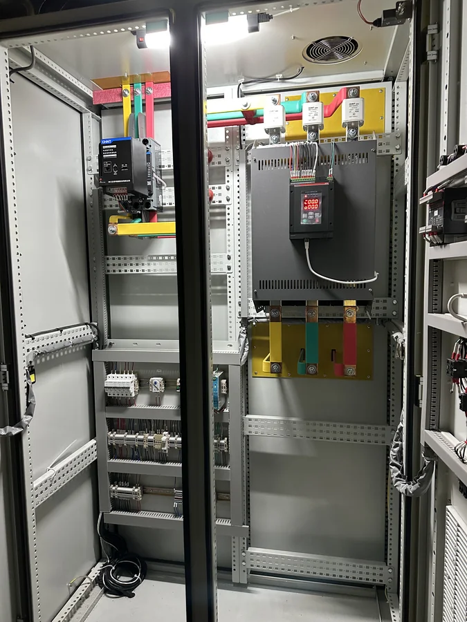
One item deserves attention: a controller on a transformer primary is an inductive-load application. Firing symmetry and any DC component, closing sequence and inrush, and the magnetisation state of the transformer should be checked together with the transformer data at the design stage. These belong to the project technical agreement and are not replaced by this article.
What does phase-angle firing solve in this duty?
The APR3 series supports three output modes: phase-angle, zero-crossing with fixed period and zero-crossing with varying period. These units use phase-angle firing because it matches the boosting load: the firing angle of the thyristors within each cycle sets the output voltage, so the output is continuously adjustable, with no whole-cycle switching events.
| Aspect | Phase-angle firing | Zero-crossing firing |
|---|---|---|
| Regulation | Firing angle sets the output voltage, continuously adjustable | Whole cycles switched; average power set by the duty ratio |
| Suited loads | Loads needing continuous smooth control, low thermal inertia | High-inertia heating loads that tolerate switching |
| Start-up behaviour | Can ramp from a low firing angle, limiting cold-state inrush | Whole-cycle switching is harsh when cold resistance is low |
| Grid effect | Generates harmonics; larger ratings need a harmonic review | Low harmonics, but resolution limited by the switching period |
| This project | Selected | Not selected |
Two notes belong here. Phase-angle firing injects harmonics into the supply - an inherent cost of the method - so circuits totalling about 3.59 MW should be reviewed against the grid short-circuit level and existing harmonics before connection, with mitigation added where needed. And the controller is the power actuator in the temperature loop: the achieved temperature control also depends on the load behaviour, the measurement feedback and the control strategy, and must be assessed against the specific duty.
What do the PROFINET module and dual LCD panels add on site?
Both options on these units serve the same site goal: less work in front of an energised cabinet, better diagnostics. The dual panels correspond to the CD position in the model code: CD is an external LCD display board, the panel mounted on the cabinet door, while the built-in LCD panel stays inside for commissioning and maintenance.
| Item | Site role | Implementation |
|---|---|---|
| PROFINET module | Power setpoint, running status, current, voltage and fault words travel over the bus to the PLC or host system for remote monitoring and logging | External module on DIN rail; Modbus RTU/TCP and Profibus are also supported and selected against the site bus standard |
| Internal panel | Parameter setting, status viewing and local start/stop during commissioning and maintenance | Built-in LCD with keypad numeric setpoint |
| Door panel (CD) | Day-to-day monitoring and operation from outside the cabinet, doors closed | External LCD display board with mounting shell; network-crystal data cable made to the cabinet dimensions |
On a continuously running glass furnace the dual panels pay off directly: routine inspection and setpoint changes happen at the closed door, so the internal components see less dust and temperature swing and operators spend less time in front of live parts. The PROFINET value grows with the number of units: the APR3 series supports multi-unit intelligent power distribution, and with the bus in place, zoned power coordination, fault localisation and run records are all handled at the host level. The exact commands, feedback data and PLC configuration requirements follow the communicator documentation and the results of project integration; panel functions, control authority and operating procedures should be set against site management requirements.
Key ratings of the two APR3-1500/M-DO-CD-V690 units
| Item | Value | Note |
|---|---|---|
| Model | APR3-1500/M-DO-CD-V690 | APR3 three-phase SCR power controller (multi-function) |
| Quantity | 2 units | One per transformer primary circuit |
| Rated output current | 1500 A | Model current position; series covers AC10-3000 A |
| Main circuit voltage | AC 690 V | Model voltage position; 690 V is an ordered voltage option |
| Control mode | Phase-angle firing | Continuously adjustable output for boosting duty |
| Connection | Transformer primary side | Transformer output feeds the boosting electrodes |
| Communication | PROFINET module | External, DIN-rail mounted |
| Panels | Dual LCD, internal + door | Door panel is the CD external LCD board |
| Combined full output | About 3.59 MW | √3 × 690 V × 1500 A × 2 units |
| Duty | Electric boosting power supply | Primary-side power regulation |
| Destination | Russia | Export project |
| Commissioned | 10 October 2026 | After site commissioning |
Under the KULUN ordering code, 1500 is the rated current position, M the MODBUS communication option, CD the external LCD display board, and V690 the AC 690 V main-circuit voltage option. The APR3 series also provides 2 analogue inputs, 2 digital inputs and 1 relay output, open-loop plus constant-current, constant-voltage and constant-power modes, and optional temperature PID with eight-segment curves; the exact combination follows the ordered model and the technical agreement.
How is commissioning sequenced for an export project?
The difference between an export project and a domestic one lies less in the commissioning steps than in the preparation before shipment and the support chain afterwards. The sequence on site was:
- Delivery inspection: nameplate model, voltage and current ratings and ordered options, with fasteners and terminals checked after long-distance transport.
- Insulation resistance and withstand test to the 690 V class, with ambient conditions recorded.
- No-load energisation and firing waveform check across firing angles, phase sequence and setpoint direction.
- Communication integration: PROFINET module against the PLC configuration, verifying every setpoint, feedback and fault-word address.
- On-load heat-up: output raised step by step as the glass bath warms, with current, voltage and power logged at each stage.
- Closed-loop tuning against the actual duty, auto-tune followed by a review of the temperature band.
- Continuous run assessment at the normal operating points, confirming the temperature swing and output stability stay inside the process window.
Three items should be settled before shipment on an export project: the site supply system and frequency against the design input, the packaging and transport plan against local climate and handling, and the language of the accompanying documents, spare-part list and remote support arrangements. Fixing these before dispatch costs far less than fixing them on site.
What to check when selecting for a similar duty
| Check item | Basis | Common mistake |
|---|---|---|
| Main-circuit voltage class and frequency | Fixed by the existing site supply, not by the equipment | Specifying the preferred value and finding a mismatch on delivery |
| Rated output current | Calculated from circuit power and duty, with margin | Sizing from hot-state resistance only, ignoring the cold start |
| Firing mode | Chosen from the cold/hot resistance gap and the process control need | Zero-crossing everywhere, repeated overcurrent at start-up |
| Transformer connection and regulation point | Primary-side regulation saves current; secondary-side regulation needs heavy thyristor paralleling; decided with the turns ratio and electrode data | Primary and secondary sides not confirmed, wiring impossible on arrival |
| Control mode | Constant voltage, current or power against the process target | Open-loop manual control where the process needs a closed loop |
| Communication | Matched to the site PLC or DCS bus standard | Bus type differs from the host system, rework on site |
| Panels and operating position | External display board chosen from cabinet layout and inspection route | External panel overlooked, every check afterwards needs the door open |
| Harmonic assessment | Based on per-circuit and system capacity and the grid short-circuit level | Equipment counted, grid effect of phase-angle firing ignored |
| Cooling and environment | From internal loss, inlet temperature and ventilation, with derating at high ambient | Device losses only, ducting and ambient temperature ignored |
What information should you prepare for an enquiry?
The two units commissioned on 10 October 2026 leave a practical reference for electric boosting projects in Russia, but selection for a similar project must still start from its own duty - not from the 1500 A and 690 V figures alone. KULUN Electric can discuss controller selection, communication options and panel configuration around the following information:
- Supply voltage, working current and the load connection arrangement.
- Whether a transformer is involved, and the cold and hot state behaviour of the load.
- The heating power control requirement and the existing control method.
- PLC model, communication protocol and the data to be exchanged.
- Cabinet installation conditions, cooling conditions and panel location requirements.
FAQ
Q: Which SCR power controllers were used in this Russian electric boosting project?
A: The project runs 2 KULUN APR3-1500/M-DO-CD-V690 three-phase SCR power controllers, commissioned on 10 October 2026. Under the KULUN ordering code, 1500 is the rated current of 1500 A, M the MODBUS communication option, CD the external LCD display board, and V690 the AC 690 V main circuit. The units connect on the primary side of the boosting transformers, fire in phase-angle mode, and reach a combined full output of about 3.59 MW.
Q: Is PROFINET communication included in this project?
A: Yes. Both APR3-1500/M-DO-CD-V690 units shipped to Russia carry a KULUN PROFINET communicator. It is an external DIN-rail module that carries power setpoints, running status, current, voltage and fault words to the site PLC or host system. The APR3 series also supports Modbus RTU/TCP and Profibus; the exact commands, feedback data and PLC configuration follow the communicator documentation and the project integration results.
Q: Why are there two operator panels, one inside the cabinet and one on the door?
A: The panels divide the work. The built-in panel stays inside for parameter setting and local operation during commissioning and maintenance; the door panel corresponds to the CD external LCD display board in the model code and serves day-to-day monitoring with the doors closed. On a continuously running boosting duty this keeps dust and temperature swing away from the internal components and reduces the time operators spend in front of live parts.
Q: Why does an electric boosting power supply need an SCR controller instead of a direct switch-on?
A: Glass barely conducts when cold and becomes an ionic conductor only when molten, so the equivalent resistance differs sharply between start-up and normal running. A direct switch-on causes heavy inrush, and running cannot follow changes in melting rate and temperature distribution. An SCR controller regulates the output continuously through the firing angle, ramps up gently from start-up, tracks the process curve in operation, and adds overcurrent, overtemperature and load-break protection.
Q: How do you choose between phase-angle and zero-crossing firing?
A: By load characteristic, not by industry habit. Loads needing continuous smooth control, with low thermal inertia or a large cold/hot resistance gap, take phase-angle firing; loads with high thermal inertia that tolerate switching, where grid harmonics matter more, take zero-crossing. Electric boosting belongs to the first group, which is why these APR3-1500/M-DO-CD-V690 units fire in phase-angle mode. The price is harmonics; a circuit totalling about 3.59 MW should be checked against the grid before connection.
Q: Is 690 V low voltage or high voltage?
A: In common practice, AC up to and including 1 kV is low voltage, so 690 V sits at the top of the low-voltage band. It is above the usual 400 V distribution level, so the insulation coordination, creepage distances and operational safety rules of the cabinet follow the 690 V class and cannot copy 400 V practice. For selection, the name matters less than three checks: the actual site supply voltage, the insulation level required, and the local operational safety rules.
Q: Why regulate on the transformer primary instead of the electrode side?
A: Current. The electrode side is low-voltage and very high-current; regulating there needs many paralleled thyristors with the sharing, cooling and reliability problems that follow. On the primary side, 690 V and 1500 A fit the APR3 series range, and the transformer maps the power to the electrodes through its ratio. A transformer primary is an inductive application, so firing symmetry and DC component, closing inrush and magnetisation must be checked against the transformer data at the design stage.
Q: Is the PROFINET module internal or external?
A: In the KULUN APR3 ordering code, Ethernet PROFINET is an optional external module mounted on a DIN rail, alongside Modbus RTU/TCP and Profibus. Select the communication form against the site PLC or DCS bus, and align the address mapping and configuration files before shipment to avoid changes on site.
Q: What do dual internal and door panels actually do?
A: The internal panel serves commissioning and maintenance: parameters, status and local start/stop. The door panel (the CD external LCD display board in the model code) serves daily operation, so inspection and setpoint changes happen with the doors closed. On a continuously running glass furnace this keeps dust and temperature swing away from the internal components and reduces the time operators spend in front of live parts. The external board comes with its own display board and mounting shell, with the data cable made to the cabinet dimensions.
Timeliness note
This article reflects project commissioning information from Sichuan Kulun Electric dated 10 October 2026 and product documentation as of October 2026, and discusses the configuration and commissioning of three-phase SCR power controllers for electric boosting duty. The model, the quantity of 2 units, the 1500 A rating, the AC 690 V main circuit, the phase-angle firing mode, the transformer primary-side connection, the PROFINET communication and the dual panels were provided by the user; transformer ratio, electrode layout and process parameters follow the site technical agreement. The power and current examples illustrate the principle only and do not represent the complete parameters of any specific project.
Related Technical Knowledge
APR3 SCR Power Controller for Industrial Furnace Heating
How to Select an SCR Power Controller for a Float Glass Tin Bath
Application Case
ST200 150 A SCR Power Control Cabinet in a Poland Glass Fiber Tank Furnace Drawing Line