

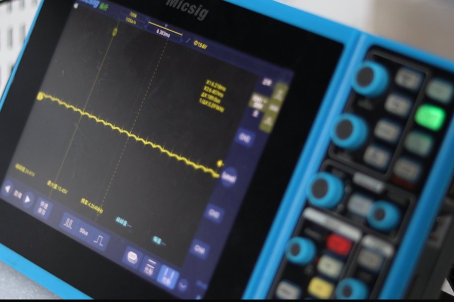
Bottom line first: the controller output reads about 1 V DC, but that reading tracks the grid. In our bench test, the APR3L, APR3 and ST200 added no significant DC of their own.
Engineers often ask: since an SCR power controller switches the mains, does it leave a DC offset behind? We put it on the bench.
What is DC offset?
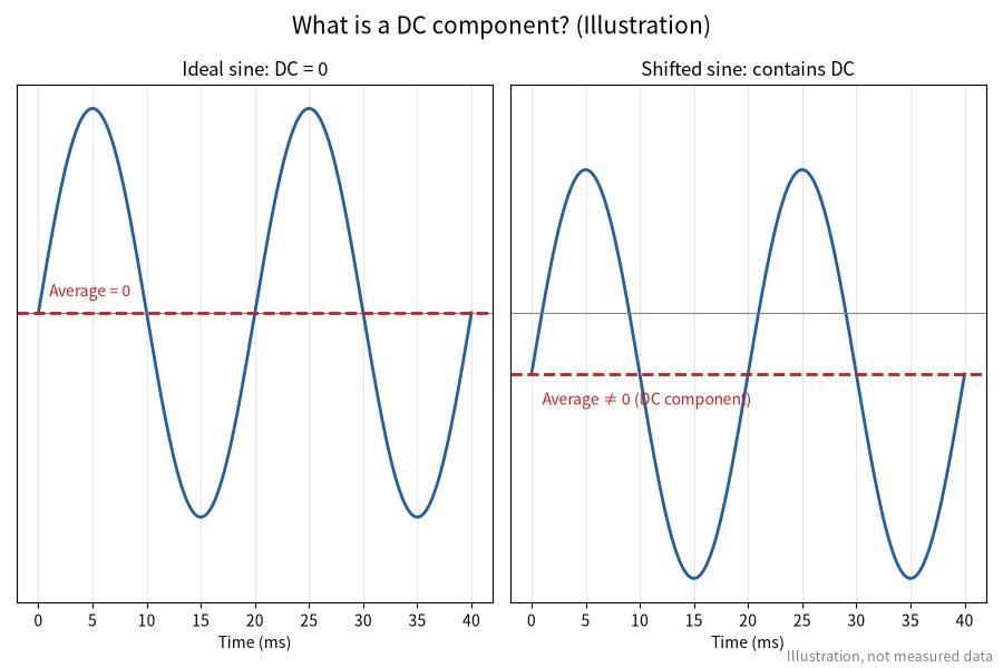
In short: if an AC waveform does not average to zero over one cycle, the remainder is the DC component.
- An ideal AC waveform has equal positive and negative half-cycles, so it averages to zero.
- If the half-cycles are unequal, the non-zero average is the DC component. (Principle, not measured.)
- Typical causes: half-wave loads, many switch-mode supplies on the grid, mismatched firing of the two SCR half-cycles.
Why does DC offset matter?
In short: a small offset goes unnoticed, a large one damages equipment, especially transformer loads.
- Transformers: core DC bias, higher magnetizing current, heat, noise, possible saturation.
- Inductive loads: current distortion and extra heating.
- Protection: fuses and protective devices may age early or trip.
How do you check your own system?
In short: baseline the grid first, then measure the controller output and compare.
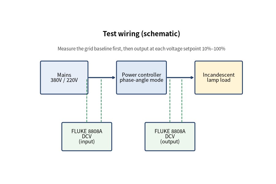
- Baseline the grid. With the controller disconnected, measure line and phase voltages on the DC range of a high-resolution DMM (5½ digit or better).
- Measure the output. Connect the load and step the output voltage setpoint from 10% to 100%.
- Record each line. For three-phase units, log AB, BC and AC at every step.
- Swap the load and repeat.
- Compare. Output close to the grid baseline means the controller isn't adding DC of its own.
Live measurements must be done by qualified personnel. Keep the control signal (0–5 V, 4–20 mA or 0–20 mA) steady during each step.

What did our test data show?
In short: both three-phase and single-phase outputs stayed in the same range as the grid baseline.
Setup:
- Meter: FLUKE 8808A 5½-digit DMM
- Firing mode: phase-angle (voltage regulation)
- Loads: two incandescent lamp loads (swapping them did not change results)
- Setpoint: output voltage setpoint, 10%–100%
- Date: 20 March 2026
Grid baseline (V)
| AB | AC | BC | AN | BN | CN |
|---|---|---|---|---|---|
| -0.93966 | -0.94448 | -0.94524 | -0.88731 | -0.88625 | -0.89926 |
Three-phase output (V)
| Voltage setpoint % | APR3L AB | APR3L BC | APR3L AC | APR3 AB | APR3 BC | APR3 AC |
|---|---|---|---|---|---|---|
| 10% | -0.53092 | -0.46573 | -0.50937 | -0.47533 | -0.57463 | -0.52063 |
| 20% | -0.82311 | -0.80384 | -0.81711 | -0.78249 | -0.84397 | -0.80937 |
| 30% | -0.95474 | -0.94183 | -0.94176 | -0.91553 | -0.96357 | -0.93876 |
| 40% | -1.11046 | -1.08321 | -1.08332 | -1.05054 | -1.09351 | -1.06351 |
| 50% | -1.06751 | -1.04953 | -1.03387 | -1.02157 | -1.05495 | -1.03324 |
| 60% | -1.04424 | -1.02902 | -1.02394 | -1.03984 | -1.03925 | -1.02565 |
| 70% | -1.03796 | -1.03627 | -1.03285 | -1.02788 | -1.04275 | -1.02115 |
| 80% | -1.04776 | -1.03538 | -1.03319 | -1.03218 | -1.04855 | -1.04931 |
| 90% | -1.04578 | -1.04028 | -1.04309 | -1.03599 | -1.05137 | -1.05274 |
| 100% | -1.05114 | -1.04082 | -1.04211 | -1.01785 | -1.03151 | -1.03341 |
| Mean (as logged) | -0.956061 | -0.954777 |
Single-phase ST200 output (V, by voltage setpoint %)
| 10% | 20% | 30% | 40% | 50% | 60% | 70% | 80% | 90% | 100% |
|---|---|---|---|---|---|---|---|---|---|
| -0.38692 | -0.56557 | -0.68681 | -0.78094 | -0.86175 | -0.93448 | -0.99231 | -0.98318 | -0.94276 | -0.82582 |
Mean (as logged): -0.796054 V.
Key takeaways
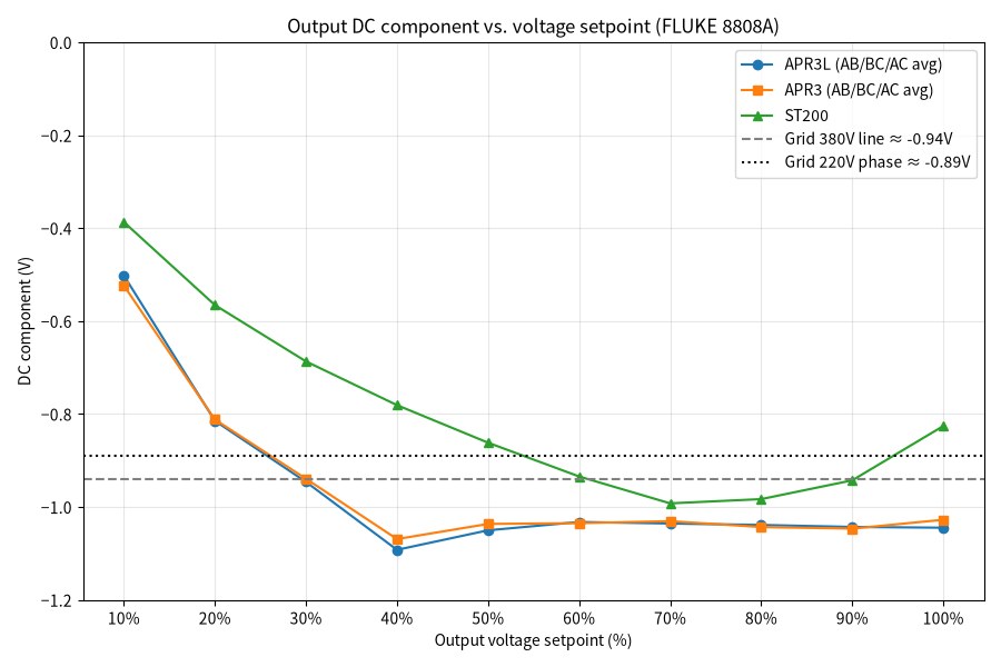
- Balanced phases: AB, BC and AC readings track closely at every setpoint.
- APR3L ≈ APR3: means of -0.956 V and -0.955 V.
- Follows conduction: lower at low setpoints (≈ -0.4 to -0.5 V), settling around -0.94 to -1.11 V from 30% up, close to the -0.94 V grid line baseline.
- ST200: -0.39 to -0.99 V, mean -0.796 V, same order as the -0.89 V phase baseline.
- Load-independent across the two incandescent loads tested.
So does a power controller create DC offset?
In short: you can measure DC at the output, but it comes mainly from the grid, not from the controller.
The grid itself carried roughly 1 V of DC in this test. A power controller switches the mains, so its output DC tracks the grid's. Under these conditions we found no significant DC added by the APR3L, APR3 or ST200.
FAQ
I measure DC voltage at the controller output. Is the unit faulty?
Not necessarily. In our test the grid itself read about -0.89 to -0.95 V DC, and the controller outputs read about -0.4 to -1.1 V, the same order. Measure the grid baseline with the controller disconnected first, then compare. Only an output clearly above the baseline calls for checking firing symmetry.
Which meter should I use to measure DC offset?
Use a high-resolution DMM, 5½ digits or better, on the DC voltage range; we used a FLUKE 8808A. A basic meter lacks the resolution to resolve readings below 1 V reliably. Live measurements must be made by qualified personnel.
Why is the DC reading lower at low setpoints?
In phase-angle mode, a low setpoint means a small conduction angle in each half-cycle, so the output is connected to the grid for a smaller share of the time. The measured grid DC shrinks accordingly. From about 30% up, readings settle near the grid baseline.
Timeliness note
This article is based on bench test data recorded on 20 March 2026 and published in October 2026. Results apply to the meter, loads and phase-angle mode described here; readings vary with grid and site conditions. Always follow the manual supplied with the unit and on-site measurements.