

High-temperature heating elements such as silicon carbide (SiC) and silicon molybdenum (MoSi2) rods change resistance during heat-up, holding, and long-term service. If the controller simply works at a fixed output voltage, the actual heating power may drift from the process setpoint. So whether to adopt constant-power control should be judged from three aspects: load change, furnace temperature curve, and supply boundaries.
First Be Clear: What Problem Does Constant-power Control Solve?
For approximately resistive loads, the relations among power, voltage, current, and resistance support basic checking:
| Relation | Meaning for on-site judgment |
|---|---|
| P = U × I | Check whether target power and measured voltage/current were collected under the same condition. |
| P = U² / R | When R changes, a fixed voltage does not mean fixed power. |
| I = U / R | With low cold-state resistance, startup current may exceed the stable high-temperature stage. |
These relations only apply to basic resistive-load analysis. A real furnace must also account for transformers, line voltage drop, the temperature controller’s output method, three-phase balance, and the power controller’s control configuration.
Why Do SiC and MoSi2 Deserve Extra Attention to the Power Loop?
The resistance of SiC and MoSi2 rods changes with temperature and service state. If output is regulated long-term only by fixed voltage or fixed firing angle, the power actually delivered to the elements may shift as resistance changes — affecting heat-up speed, zone stability, and zone-to-zone consistency.
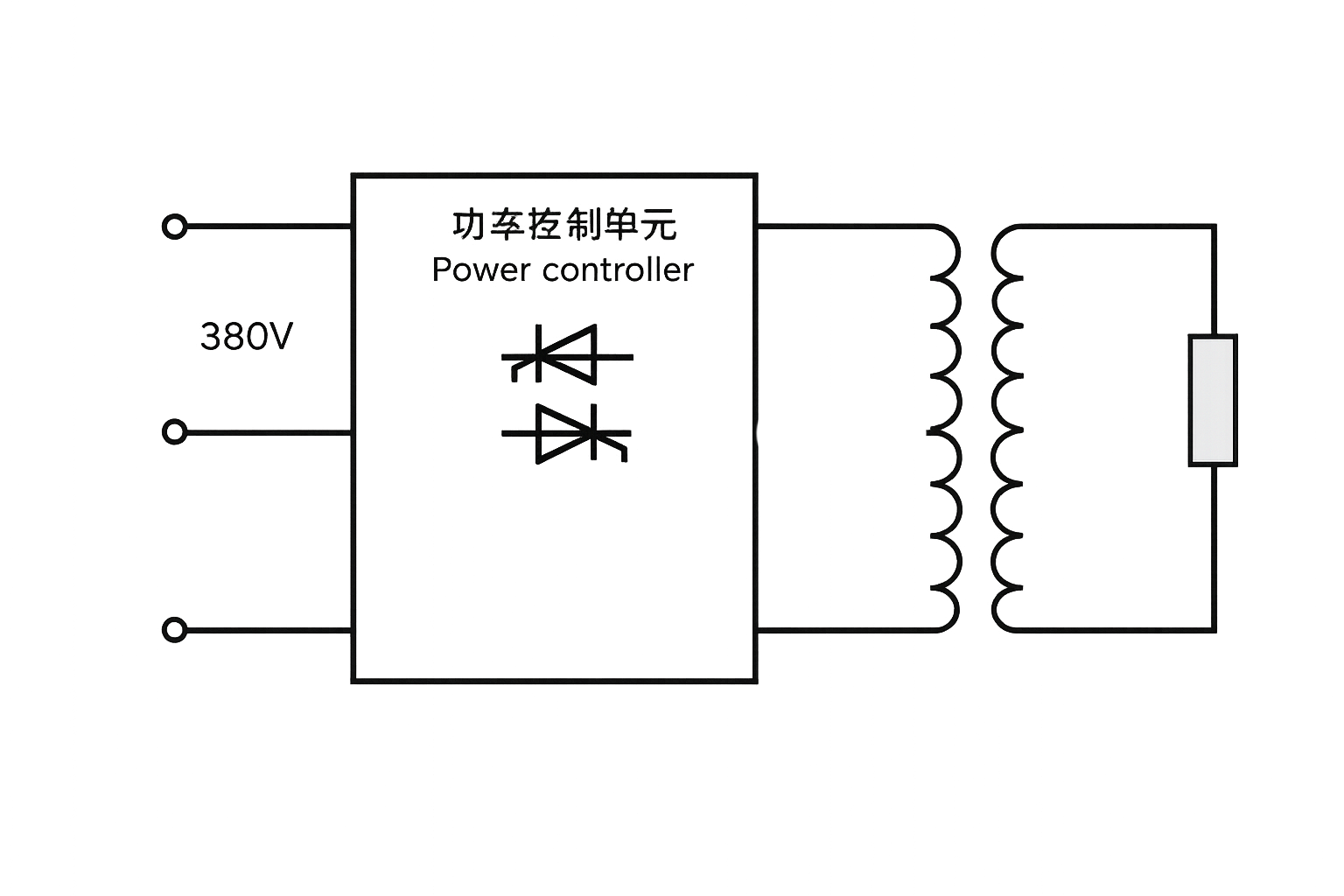
High-temperature heating control usually requires checking the match among power controller, transformer, and heating elements together.
Constant-power control does not replace temperature control on its own. A common control chain is: the temperature controller issues a power demand from the temperature deviation, and the power controller regulates output from voltage and current feedback. Whether to use constant voltage, constant current, or constant power should correspond to the element characteristics and control target.
Engineering Conditions to Collect Before Selection
| Check item | What to confirm | Direct impact |
|---|---|---|
| Elements & zones | SiC or MoSi2 model, number of zones, per-zone connection | Per-zone voltage, current, and regulation range |
| Cold/hot characteristics | Resistance at cold state and working temperature, or maker’s electrical data | Startup current limiting, transformer taps, capacity checks |
| Supply conditions | Phase system, incoming voltage, transformer capacity, allowed grid fluctuation | Power devices, protection, and distribution scheme |
| Control interface | Temperature-controller output, setpoint signal, PLC or communication requirements | Closed-loop method and site interlocks |
| Operating conditions | Heat-up curve, holding time, continuous-duty requirement, environment and cooling | Control parameters, cooling, and maintenance plan |
When Power Deviation Appears, What to Check First
- Slow heat-up or failure to reach setpoint: first check each zone’s actual voltage, current, element condition, transformer taps, and control setpoint — don’t just raise the setpoint.
- Cold-start overcurrent: confirm cold-state resistance, soft-start ramp, current-limit value, fast fuse, and current-feedback matching.
- Growing zone-to-zone difference: check element aging, wiring contact, temperature feedback, and per-zone power output separately — don’t just compare total power.
- Obvious grid fluctuation at deep phase control: evaluate firing angle, harmonics, power factor, transformer, and site grid requirements together.
Choosing Among Constant Power, Constant Voltage, and Constant Current
For high-temperature heating loads with noticeable resistance change where the process cares about stable actual heating power, evaluate constant-power control. When a specific loop current must be limited, focus on constant-current and current-limiting strategy. Where output voltage has explicit requirements, prioritize the constant-voltage boundary. The control mode cannot be fixed by the heating-element name alone — it must follow complete electrical parameters and process conditions.
FAQ
Must MoSi2 rods always use constant-power control?
Not necessarily. Adoption depends on element resistance change, temperature target, supply structure, and site control requirements; some conditions also need constant-current limiting or constant-voltage boundaries.
Can selection be done from the element’s rated power alone?
No. Per-zone voltage, current, cold/hot characteristics, zone count, supply phases, control interface, and continuous-duty conditions are all needed to verify regulation range and protection configuration.
When cold-state current is too high, change parameters first or change equipment?
First confirm the element’s cold-state data, wiring, transformer, soft-start, and current-limit parameters. Before the cause is found, it is not advisable to simply raise the current limit or swap in a larger unit.
Related Products, Knowledge, and Cases
For three-phase high-temperature furnace control, see the APR3L, APR3, and APR3S three-phase power regulators; for single-phase zones, evaluate the ST200. On the boundaries among SCR, layered SCR, and IGBT options for MoSi2 heating, read MoSi2 heating control options compared; for sintering-furnace conditions, see the APR3 & ST200 lithium-battery sintering pusher kiln case.