

Short answer: thyristors connected in series do not share voltage automatically. Differences in leakage current, junction capacitance, reverse recovery and trigger timing push the voltage onto one device, which breaks down first and can take the whole string with it. Series operation therefore needs grading: a parallel resistor for steady-state sharing, an RC snubber for transient sharing, plus trigger synchronisation and overvoltage protection. This guide gives the resistor sizing calculation, RC snubber design principles and the series-count margin method for 3 kV/6 kV/10 kV high-voltage power control cabinets.
Why Don't Thyristors in Series Share Voltage Automatically?
In high-voltage thyristor power controllers, high-voltage rectifiers, soft starters and large AC power control systems, several thyristors (SCRs) are connected in series when the blocking voltage of a single device is not enough. Simply putting devices in series, however, does not give a working design.
Suppose two thyristors with the same voltage rating are placed in series across a 3000 V supply. Ideally each would take 3000 ÷ 2 = 1500 V. In practice they do not. Even devices of the same type and the same production batch differ in reverse leakage current, junction capacitance, gate trigger characteristics and recovery time.
Take two series thyristors in the blocking state: SCR1 leaks 5 mA and SCR2 leaks 10 mA. With no grading network, the two devices present different equivalent impedances, so the voltage is not split 1:1 and one thyristor carries a clearly higher blocking voltage. This is the real reason why series thyristors need voltage grading.
From an engineering standpoint, voltage grading has two parts: static sharing and dynamic sharing. They solve different problems and neither can replace the other.
What Is Static Voltage Sharing? How Do You Size the Grading Resistor?
Static sharing means making the DC or power-frequency steady-state voltage across series devices as uniform as possible while they block. The usual method is to connect a grading resistor R in parallel with each thyristor.
A blocking thyristor conducts a leakage current, and that current varies from device to device. If an external resistor current is added that is much larger than the device leakage current, the voltage division of the whole string is set mainly by the resistors rather than by the unstable leakage characteristics of the thyristors. This gives the basic design rule:
The grading resistor current must be significantly larger than the maximum thyristor leakage current and its spread.
The resistance is then R ≈ U / IR, where R is the resistor across one thyristor, U is the blocking voltage one thyristor is designed to carry, and IR is the resistor current.
Worked example: one thyristor carries 2000 V and the grading resistor current is set to 20 mA, so R = 2000 ÷ 0.02 = 100 kΩ. The resistor dissipation is then P = U² / R = 2000² ÷ 100000 = 40 W. Grading resistors in high-voltage strings dissipate real power, so the design must cover power margin, voltage rating, temperature rise and long-term reliability, not just resistance. In many high-voltage units a single grading resistor is built from several high-voltage resistors in series.
Why Is a Grading Resistor Not Enough?
The grading resistor solves steady-state voltage division. The most dangerous moment for a thyristor, however, is when the voltage changes fast.
During AC commutation, turn-off, load steps or grid transients, the two thyristors see different junction capacitances and recovery behaviour, and the voltage can slew at hundreds to thousands of V/μs. At that speed a resistor of tens or hundreds of kilohms cannot redistribute the voltage quickly enough.
That brings in the second problem: dynamic voltage sharing.
What Is Dynamic Voltage Sharing?
Dynamic sharing deals with voltage division at the instants of turn-on, turn-off and commutation. The usual method is an RC snubber network across each thyristor, understood as a series "R + C" branch in parallel with the device.
The capacitor C limits the rate of voltage rise across the thyristor and, through its charge and discharge behaviour, improves transient voltage division. When the voltage across one thyristor rises sharply, the capacitor absorbs part of the transient energy so the voltage cannot appear across that device instantaneously, which lowers the overvoltage risk.
The basic relation is i = C × du/dt: for a given transient current, a larger capacitance means a lower du/dt across the thyristor. That is the principle behind the dynamic sharing capacitor.
What Does the Resistor in the RC Snubber Do?
If the capacitor does the grading, why add a resistor in series? Because a capacitor alone does not solve everything: when the thyristor turns on, the energy stored in the capacitor has to go somewhere, and without a current-limiting resistor it can discharge through the thyristor as a large current spike.
The resistor in the RC network therefore does three things:
- Limits the capacitor discharge current;
- Damps LC ringing;
- Reduces the current stress on the thyristor at turn-on.
That is why real designs use a calculated and tested RC snubber network rather than a bare capacitor. Bigger is not better: too much capacitance increases reactive current and turn-on transient current; too little resistance increases the discharge spike; too much resistance weakens the damping.
RC parameters for high-voltage thyristors are set from a combination of factors: system operating voltage, thyristor voltage rating, permitted du/dt, number of devices in series, load type, stray inductance of the loop, switching frequency, commutation behaviour and the actual overvoltage waveform.
What Is Voltage Sharing in Essence?
Seen electrically, voltage sharing for series thyristors solves two problems on two different time scales:
| Sharing method | Main component | Problem it solves | When it acts |
|---|---|---|---|
| Static sharing | Parallel resistor R | Steady-state unbalance caused by leakage current spread | Steady-state blocking |
| Dynamic sharing | RC network | Transient overvoltage from junction capacitance and recovery-time spread | Turn-on, turn-off, commutation |
| Overvoltage protection | MOV, TVS, snubber circuits | External surges and abnormal overvoltage | Abnormal transients |
A reliable high-voltage series string is therefore not built around a single grading resistor. It uses the combination of static sharing + dynamic sharing + overvoltage protection + synchronised triggering.
Why Is Trigger Synchronisation Just as Important?
Besides "how the voltage divides when blocking", there is "whether all devices turn on together". Suppose three thyristors are in series and two have fired while the third is still off because its gate pulse is weaker or delayed. For a short instant almost the entire string voltage can appear across that one device. This is turn-on dynamic unbalance.
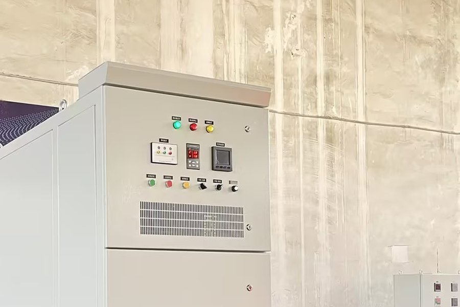
High-voltage series strings therefore need: synchronised trigger pulses, equal gate pulse amplitude, sufficient pulse width, identical isolation performance in the trigger circuits, and symmetrical connection layout. In high-voltage power control cabinets, the quality of the trigger system directly affects long-term reliability. KULUN's APR3L-HV cabinet, for example, uses a dual-isolation scheme of fibre-optic triggering plus inductive triggering, which keeps triggering synchronised while preventing high voltage from reaching the low-voltage control area.
Why Can't the Series Count Be Calculated by Dividing Voltage Ratings?
If the system peak voltage is 10 kV and the thyristor repetitive peak rating is 4.5 kV, then 10 ÷ 4.5 ≈ 2.22 suggests three devices are enough. Real designs cannot be done this way, because the budget must also cover grid fluctuation, commutation overvoltage, transient surges, dynamic unbalance, parameter spread and long-term ageing.
The voltage actually applied to a thyristor must therefore carry a sufficient margin. Designers normally fix the permitted per-device working voltage first and then set the number in series, rather than dividing the system voltage by the device rating. This is one of the main differences between high-voltage thyristor systems and ordinary low-voltage SCR power controllers.
What Is Most Often Overlooked on Site?
Voltage grading is not only a matter of calculating R and C. Five points deserve attention in real equipment:
1. Device screening. Use thyristors of the same type and batch, with key parameters as close as possible, in one series string.
2. Symmetrical layout. Differences in busbar length, connection style and stray inductance also shift the dynamic voltage division.
3. RC component ratings. Do not look only at capacitance and resistance; check pulse voltage rating and transient power capability.
4. Measure the real dynamic waveforms. A multimeter reading of average voltage cannot tell you whether dynamic sharing is healthy. During commissioning, observe the per-device voltage waveform at commutation and turn-off.
5. Grading does not mean "perfectly equal". The design target is not identical voltage at every instant, but that under the worst operating condition the peak voltage on every device stays inside its safe operating area.
FAQ
Q: Can two 4.5 kV thyristors in series be used directly on a 10 kV system?
A: No. Sizing cannot be done by 10 ÷ 4.5 ≈ 2.22 alone. A 10 kV system has a maximum equipment voltage of 12 kV and a phase-voltage peak of about 9.8 kV; after applying a voltage margin factor of 2.0–2.5 and a series sharing factor of 0.85–0.90, a 10 kV power control cabinet typically needs four high-voltage thyristors in series per phase. An AC controller needs anti-parallel pairs, so the device count doubles. The manufacturer should supply the calculation sheet rather than relying on a simple division.
Q: Is a smaller grading resistor always better?
A: A smaller resistor passes more current and makes steady-state division "stiffer", but dissipation follows P = U²/R and rises sharply as the resistance falls. The practical approach is to make the resistor current significantly larger than the maximum thyristor leakage current and its spread, then check power margin, temperature rise and long-term reliability, and build the resistor from several high-voltage parts in series when needed.
Q: Is a larger snubber capacitor always better?
A: No. A larger capacitor lowers du/dt across the thyristor, but it also increases reactive current and the discharge spike at turn-on, and the series resistor must provide matched damping or the LC loop will ring. RC values should be set from system voltage, permitted du/dt, number of devices in series, load type, stray inductance, switching frequency and commutation behaviour, then verified against measured waveforms.
Q: How do you check on site whether series grading is healthy?
A: A multimeter reads average voltage and cannot show the distribution at commutation or turn-off. Use an oscilloscope with high-voltage differential probes and compare the per-device voltage waveforms and peak values at those instants. The pass criterion is not equality, but that the peak voltage on every device stays within its safe operating area under the worst case.
Timeliness note
This article is based on general engineering practice and product documentation current in September 2026. The resistor sizing example, RC selection principles and series-count method given here are common engineering approaches; final parameters must come from the manufacturer's design calculation sheet, device datasheets and the project technical agreement.
Related Technical Knowledge
How to Select a High-voltage Power Control Cabinet
SCR Cabinet Cooling: Heat Load, Airflow and Ducting
Application Case
KULUN 10 kV High-voltage Power Control Cabinet Passes Factory Tests