

Bottom line first: on a KULUN TTPR three-phase SCR power controller with the same resistive heater load, phase-angle firing produced far more load-voltage harmonic distortion than zero-cross (fixed-period) firing. Phase-angle THD-R was 86.66% at a 10% setpoint, 53.66% at 50%, 26.24% at 90% and 1.14% at 100%. Zero-cross fixed-period THD-R stayed at about 1.02-9.08% across all setpoints.
The KULUN engineering department ran the test and measured the load phase voltage. The same firing mode behaves the same way on other KULUN power controllers, so the results are representative.
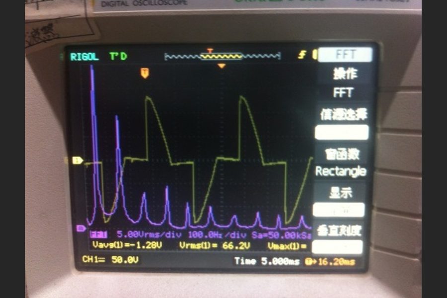
How Was the Test Set Up?
The unit belongs to the TTPR series; see the TTPR Three-phase SCR Power Controller (Standard). Phase-angle and zero-cross firing were run on the same heater load; the zero-cross mode tested was fixed-period.
Steps of the test
- Wiring: anti-parallel thyristors per phase, 3 × 14 Ω heating wire in star.
- Sampling: voltage between the heater star point and the phase A output.
- Analysis: setpoint from 10% to 100% in 10% steps, oscilloscope FFT at each step.
| Item | Test condition |
|---|---|
| Unit under test | KULUN TTPR series three-phase SCR power controller |
| Supply | 400 V / 50 Hz |
| Load | Resistance heating wire, 3 × 14 Ω, star connection |
| Measured quantity | Load phase voltage (via 380 V/9 V transformer, 10X probe) |
| Instrument | Digital oscilloscope, reading accuracy ±1.0% |
| Analysis | Oscilloscope FFT, rectangular window |
| Ambient temperature | 28 °C |
| Setpoints | 10% to 100%, ten points per mode |
| Not measured | Power factor, supply-side current |
| Data source | KULUN engineering department bench test |
What Do Phase-Angle and Zero-Cross Firing Mean?
- Phase-angle: every half-cycle conducts, but turn-on is delayed, so each half-wave is chopped.
- Zero-cross fixed-period: whole cycles switch on at the voltage zero crossing; power is set by the number of ON cycles in a fixed period.
In this article, "zero-cross" always means fixed-period. Phase-angle chops the waveform; zero-cross chops the cycle train.
How Far Apart Are Zero-Cross and Phase-Angle in Measured THD?
The table gives measured THD-R of the load phase voltage, referenced to total RMS. Fluctuating fixed-period readings are shown as ranges.
| Setpoint | Phase-angle THD-R | Zero-cross fixed-period THD-R |
|---|---|---|
| 10% | 86.66% | 4.18% |
| 20% | 77.94% | 4.16% |
| 30% | 70.44% | 4.17-9.08% |
| 40% | 62.78% | 1.22-4.15% |
| 50% | 53.66% | 1.02-9.01% |
| 60% | 44.19% | 1.26-4.19% |
| 70% | 37.85% | 1.22-9.06% |
| 80% | 32.78% | 1.25-4.18% |
| 90% | 26.24% | 1.25-4.17% |
| 100% | 1.14% | 1.26% |
Three takeaways
- Phase-angle distortion falls as the setpoint rises: 86.66% at 10%, 1.14% at 100%.
- Fixed-period distortion stays low at every setpoint: 1.02-9.08%.
- At full output the two converge: 1.14% versus 1.26%.
Which Harmonic Orders Dominate in Phase-Angle Firing?
The 5th, 7th, 11th and 13th dominate. The 3rd, 9th and 15th stay at a few percent, and the 2nd reads 0.00%.
| Setpoint | Output (V RMS) | 5th | 7th | 11th | 13th | THD-F | THD-R |
|---|---|---|---|---|---|---|---|
| 10% | 40.3 | 95.03% | 86.79% | 72.14% | 58.17% | 173.81% | 86.66% |
| 20% | 80.1 | 84.12% | 67.68% | 37.86% | 25.29% | 124.31% | 77.94% |
| 30% | 120.1 | 72.61% | 50.53% | 22.22% | 21.38% | 99.01% | 70.44% |
| 40% | 160.2 | 60.59% | 36.37% | 21.31% | 20.31% | 80.25% | 62.78% |
| 50% | 199.9 | 49.18% | 24.86% | 19.44% | 13.21% | 63.63% | 53.66% |
| 60% | 239.7 | 38.54% | 18.35% | 14.46% | 10.10% | 49.19% | 44.19% |
| 70% | 279.2 | 31.73% | 14.49% | 12.64% | 9.00% | 40.91% | 37.85% |
| 80% | 319.8 | 26.68% | 13.07% | 11.31% | 7.07% | 34.63% | 32.78% |
| 90% | 360.4 | 19.43% | 13.73% | 6.73% | 7.40% | 27.34% | 26.24% |
| 100% | 394 | 0.75% | 0.62% | 0.27% | 0.45% | 1.18% | 1.14% |
Why these orders (principle, not measured)
- Symmetrical firing on both half-cycles cancels even harmonics.
- In a three-wire star load, triplen harmonics cannot build up.
- The lower the setpoint, the more of each half-wave is cut, so these orders grow.
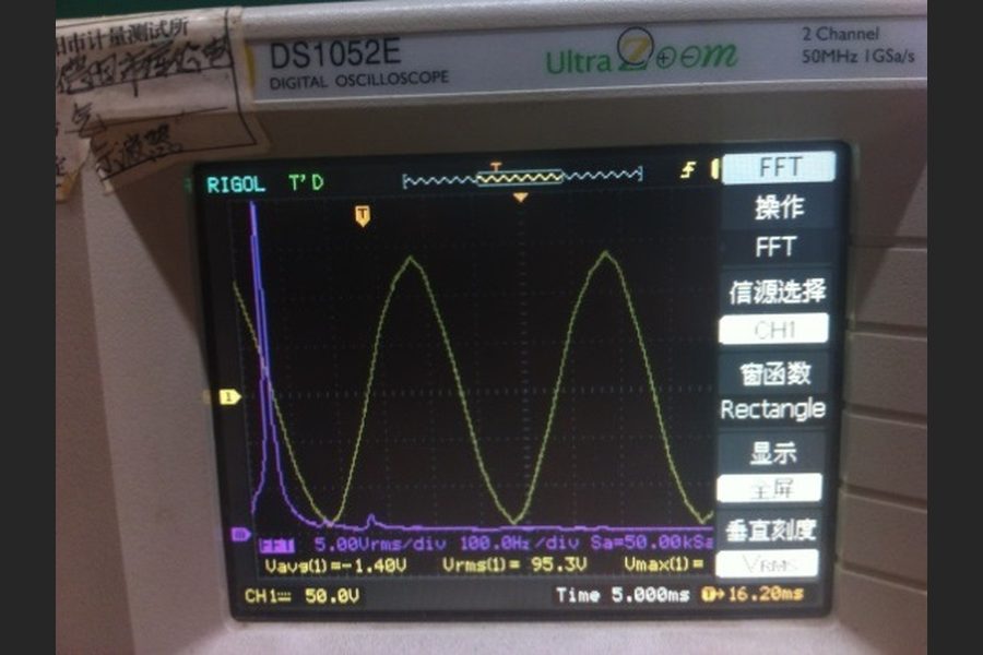
At 100% the load voltage is close to a sine wave: 5th harmonic 0.75%, THD-R 1.14%.
Why Do Zero-Cross Readings Fluctuate?
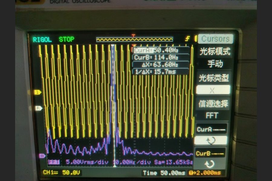
- The test record notes measurement error from intermittent switching; on-site measurement should prevail.
- Principle: the share of ON and OFF cycles may differ in each FFT window.
- Screenshots show components below 50 Hz and interharmonics, which the tables do not quantify.
Use fixed-period figures for magnitude and trend, not decimal-level comparison.
What Is the Difference Between THD-R and THD-F?
THD-F divides by the fundamental RMS; THD-R divides by the total RMS. They diverge when distortion is high.
| Definition | Denominator | Phase-angle 10% | Phase-angle 50% | Phase-angle 100% |
|---|---|---|---|---|
| THD-F | Fundamental RMS | 173.81% | 63.63% | 1.18% |
| THD-R | Total RMS | 86.66% | 53.66% | 1.14% |
GB/T 14549-1993 defines total distortion against the fundamental, which corresponds to THD-F.
Can These Figures Show Compliance With a Grid Harmonic Standard?
No. The data supports a side-by-side comparison of the two firing modes only. It cannot be used to judge whether any limit is exceeded.
Current Chinese standard limits
GB/T 14549-1993, Power Quality - Harmonics in Public Supply Network, is the current standard.
| Nominal voltage | Total voltage THD | Odd harmonic voltage | Even harmonic voltage |
|---|---|---|---|
| 0.38 kV | 5.0% | 4.0% | 2.0% |
Standard method versus this test
| Aspect | GB/T 14549-1993 | This KULUN test |
|---|---|---|
| Measuring location | Point of common coupling on the public grid | Load phase voltage at the controller output |
| THD reference | Fundamental | THD-F and THD-R recorded; main table uses THD-R |
| Statistics | 95% probability value over the measuring period | Single readings or fluctuation ranges |
| Harmonic orders | Typically 2nd to 19th | Up to 15th (phase-angle); 2nd only (fixed-period) |
| Instrument | Instrument class requirements apply | Digital oscilloscope FFT |
Three caveats
- The standard covers grid voltage at the point of common coupling; this test measured voltage on the load side.
- The standard references the fundamental; the main table here uses total RMS.
- The standard takes a 95% probability value; this test used single readings.
To assess grid impact, measure at the supply side with a power quality analyser. Supply current and power factor were not measured here.
How Should the Results Inform Selection?
Steps for selection
- Load: only a resistive load was tested; do not apply these figures directly to inductive loads.
- Setpoint: long operation at low setpoints means high distortion with phase-angle; near full output the gap is small.
- Process: choose phase-angle for continuously adjustable voltage; consider fixed-period first for low load-voltage distortion.
What Are the Limits of This Test?
- One load only: 3 × 14 Ω resistive heating wire.
- Load phase voltage only; no supply current or power factor.
- Oscilloscope FFT; fixed-period records only the 2nd harmonic and THD-R.
FAQ
Why are the 5th, 7th, 11th and 13th harmonics so large with phase-angle firing?
Phase-angle firing cuts part of every half-wave. Symmetrical firing cancels even orders, and a star load suppresses triplen orders. In the KULUN TTPR test at 10%, the 5th was 95.03%, the 7th 86.79%, the 11th 72.14% and the 13th 58.17%.
Why do zero-cross harmonic readings fluctuate?
Fixed-period firing switches whole cycles, so the ON/OFF share may differ in each FFT window. The KULUN TTPR record notes error from intermittent switching and says on-site measurement should prevail. Measured THD-R ranged from 1.02% to 9.08%.
Is load-voltage distortion the same as grid-side harmonics?
No. GB/T 14549-1993 sets a 5% total voltage THD limit for 0.38 kV at the point of common coupling, referenced to the fundamental and taken as a 95% probability value. This TTPR test measured load phase voltage, so it compares the two firing modes only and cannot show compliance.
Timeliness note
Based on a KULUN engineering department test of a TTPR series controller, compiled as of October 2026. Actual harmonics depend on the load and supply-side measurement on site; these figures are not a guarantee for any project.