

Bottom line first: analog and fully digital SCR power controllers share the same thyristor power stage; the difference sits in the control circuit. Analog units use analog circuitry with potentiometers for setpoint and limiting, while fully digital units use a digital control board with keys, display, and communications. Across 26 compared parameters, only three things genuinely drive a retrofit decision: whether the unit can display, whether it can be set, and whether it can be programmed into a system.
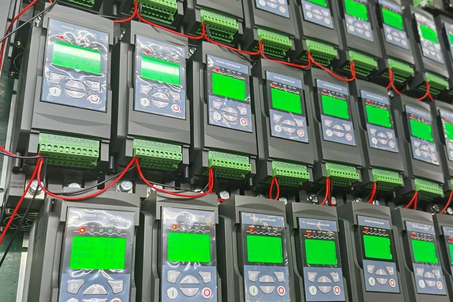
What is the core difference between analog and fully digital power controllers?
The core difference is the control circuit, not power capability. An analog controller uses analog circuitry plus potentiometers for setpoint and limiting; a fully digital controller uses a digital control board with keys, display, and communications. On the same thyristor rating, both deliver identical output — yet the number of settable parameters differs by dozens of items.
On an analog unit the setpoint is a single analog signal, ramp time is tuned by a potentiometer knob, and start/stop relies on an external switch. Changing the current limit, overcurrent threshold, or three-phase imbalance threshold means swapping components or jumpers on the board — with no digital record and no parameter backup. A fully digital unit turns all of these into software parameters. KULUN product documentation released in November 2026 shows its fully digital models carry more than 150 built-in parameters (the count covers function selections, protection settings, and factory calibration values); P, I, D, current limit, protection thresholds, and ramp times are all set from the panel and retained through power loss.
Telling which class a unit belongs to takes one look at its parameter menu — no need to open the cabinet: a parameter menu, fault codes, and a comms port mean digital architecture; only potentiometers and DIP switches mean analog. Settable parameters mean the same model moves to a different load without hardware changes.
26 parameters compared: where do the gaps concentrate?
The 26 parameters sort into three layers by "what a retrofit has to touch": the display layer asks whether information is visible, the settings layer asks whether parameters can change, and the programming layer asks whether interfaces connect. Only the programming layer usually requires new terminal wiring; display and settings differences add no wiring but directly change inspection and commissioning routines.
| Item | Analog | Fully digital (KULUN) | Retrofit impact |
|---|---|---|---|
| Product architecture | Analog circuitry | Digital control board | Architecture differs; power capability unchanged |
| Control supply | AC 220 V ±5% | AC 85–265 V, 50/60 Hz | No rewiring; wider grid tolerance |
| HMI | None | LED or LCD display + keypad | No rewiring; commissioning becomes visible |
| Current/voltage display | None | Power, current, voltage, energy (true RMS) | No rewiring; external meters become optional |
| Control accuracy | No data in source table | Manufacturer-rated better than 0.2% | Figures not directly comparable |
| Stability | No data in source table | Manufacturer-rated better than 0.1% | Figures not directly comparable |
| Software functions | None | 150+ built-in parameters | No rewiring |
| PID parameters | None | P, I, D digitally settable | No rewiring |
| Current limit | None | Digitally settable | No rewiring |
| Overcurrent threshold | None | Digitally settable | No rewiring |
| Three-phase imbalance threshold | None | Digitally settable | No rewiring |
| Ramp up/down time | Potentiometer adjustment | Digitally settable | No rewiring |
| Start/stop control | External switch | External switch, panel, or comms | May add wiring |
| Setpoint signal | Analog only | Analog, panel, or comms | May add wiring |
| Feedback source | Not configurable | Current, voltage, or power selectable | No rewiring |
| Firing mode | Not configurable | Phase-angle or zero-cross selectable | No rewiring |
| Feedback mode | Phase-angle open loop, zero-cross open loop | Phase-angle: 4 modes (open loop, constant current, constant voltage, constant power); zero-cross: 5 modes (fixed-cycle open loop, variable-cycle open loop, constant voltage, constant current, constant power) — 9 in total | No rewiring |
| Analog output signals | Not programmable | Current, voltage, power, setpoint %, output % | Requires wiring |
| Digital input signals | Not programmable | Fault reset, run enable, E-stop, external fault | Requires wiring |
| Digital output signals | Not programmable | Fault, running | Requires wiring |
| Protection functions | Overcurrent, overheat, supply protection — 3 items | Overcurrent, imbalance, supply fault, frequency fault, thyristor shoot-through, load break, overheat, comms fault, load aging alarm — 9 items | No rewiring |
| Protection enable | None | Alarm-and-trip or alarm-only settable | No rewiring |
| Fault memory | None | Yes | No rewiring |
| Smart fan | None | Real-time temperature sensing, auto start/stop | No rewiring |
| Circuit board | Low cost, noise-prone, parameters hard to retain | Strong noise immunity, versatile, easy to integrate and serialize | Vendor description, no figures |
| Communications | None | Modbus, Profibus, Profinet | Add wiring or a gateway |
Read the table in layer order instead of comparing "yes" and "no" row by row. The display layer decides inspection efficiency: when the panel shows power, current, voltage, and energy, three external meters are no longer needed. The programming layer decides integration cost: 5 programmable analog outputs, 4 digital input functions, and 2 digital output states do not change single-unit capability, but they decide whether the unit joins the existing PLC and host architecture. Select by power and current alone, and you may find the unit cannot connect to the system.
The 9 feedback-mode combinations deserve a separate look: one unit switches between phase-angle and zero-cross firing, and between open loop, constant current, constant voltage, and constant power — a direct result of digital architecture. An analog unit offers only phase-angle open loop and zero-cross open loop; changing the feedback object means changing the board. For inductive loads such as transformers, zero-cross control normally runs fixed-cycle only, paired with magnetizing soft start; variable-cycle mode does not suit this load class.
The analog-side values in the table come from KULUN's November 2026 comparison material on conventional analog models, and the digital-side values from KULUN product documentation. "Customer value" statements reflect the manufacturer's perspective rather than third-party testing; specific figures from other analog products may differ per project.
Protection items grow from 3 to 9: where is the added value?
The gain is not a vague "safer" claim but fault localization to a specific cause: alarm codes turn "it tripped" into "which class of cause tripped it". Analog units carry only overcurrent, overheat, and supply protection; after a trip, technicians measure point by point to locate the fault. The 9 digital items split common failure paths into separate alarms.
Four of the nine are structurally hard for analog designs: thyristor shoot-through requires judging whether the device has lost blocking capability, load break requires judging whether the loop has opened, frequency fault requires judging supply frequency deviation, and comms fault requires judging bus interruption. These are diagnostic functions built on logic, not threshold comparison — costly in analog circuitry, but only a few lines of judgment on a digital board.
Load aging alarm belongs to the trend class, unlike instant faults such as overcurrent or shoot-through: once resistance drifts, the same output percentage delivers different power, and the alarm prompts maintenance to plan replacement. This item can be set to alarm-only or alarm-and-trip via the protection enable parameter. For loads whose resistance rises with service time, such as silicon carbide rods, alarm-only mode reduces unplanned downtime.
More protection items also carry a cost. With parameters set wrong, the extra items become sources of false alarms; if alarm-and-trip and alarm-only are set the wrong way round, a condition that should trip becomes alarm-only. After a retrofit, run one full protection-setting calibration and record how each item acts.
Which three interfaces does a retrofit touch first?
A retrofit really touches three interfaces: control supply, setpoint and feedback, and communications. The power stage and cooling conditions do not change with control architecture — current, voltage, and cooling method are still checked against the original design, so the workload can be estimated in advance.
- Control supply: analog units are designed for AC 220 V ±5%, while fully digital units accept AC 85–265 V. The existing 220 V control supply carries over directly; where site voltage runs low or fluctuates, the wide-range input saves a voltage-stabilizer retrofit.
- Setpoint and feedback: the original 4–20 mA or 0–10 V setpoint carries over unchanged, as both architectures accept analog input. When switching to panel or comms setpoint, confirm whether the PLC analog output still needs to stay, and whether feedback comes from current, voltage, or power.
- Communications: choosing among Modbus, Profibus, and Profinet depends on the protocol the host system already runs. Adding a bus means more than one cable — shielded twisted-pair routing, termination resistor placement, station addressing, and baud rate all need to be fixed before shutdown.
- Parameter backup: archive the final parameter table so a future board or unit swap restores settings directly, without retuning.
The fourth item is the one most often skipped. Parameter backup does not affect power-up or acceptance, but it is new work introduced by digital architecture — an analog unit has no parameters to back up, so legacy workflows never included this step.
When is a fully digital controller unnecessary?
For a standalone unit with a single analog setpoint, no remote monitoring, and an existing analog spare-parts system, staying analog is simpler. The cost of going fully digital lies not only in the device but also in parameter management, comms maintenance, and staff training.
Four situations support this judgment — meeting three or more means no rush to retrofit:
- Single load: the unit drives one fixed load, the process stays unchanged for years, and no per-product parameter switching is needed.
- No integration need: no PLC or host connection; all operation happens at the machine, and nobody reads the running data.
- No maintenance capability: the site lacks comms maintenance skills, so a bus would add faults nobody can troubleshoot.
- Spares secured: spare parts for the original unit are reliably sourced, and repair response beats the commissioning cycle of a new unit.
A retrofit also carries reverse risks. Settable parameters can be mis-set, so permission management and backup routines are needed; comms bring convenience plus a new failure point — comms fault appears as one of the nine protections; spares shift from generic analog boards to model-specific digital boards, and inventory strategy must follow.
Weigh three accounts when deciding: spare-part variety, commissioning time, and fault-localization time. Only when the third drops clearly does a retrofit have justification; if all three stay flat, the retrofit only adds complexity.
Which eight items should you check before a retrofit?
Check the following eight items one by one before shutdown, and the retrofit will not stall for missing information. The first four decide selection; the last four decide maintainability after commissioning. Each carries a clear criterion, so results go straight into the retrofit plan instead of waiting for the equipment to arrive.
| Check item | What to check | Criterion |
|---|---|---|
| Load type | Resistive, inductive, SiC rods, MoSi2 elements, transformer | Decides phase-angle vs zero-cross firing |
| Setpoint source | 4–20 mA, 0–10 V, panel, comms | Decides whether terminal wiring changes |
| Control supply | Voltage range; shared circuit with other devices? | Usable directly within AC 85–265 V |
| Host protocol | Modbus, Profibus, Profinet | Decides gateway and shielded cabling |
| Protection settings | Overcurrent, imbalance, frequency, load-break thresholds | Set from measured load values and record |
| Cooling conditions | Ambient temperature, cabinet airflow, filter condition | Check derating per manual |
| Parameter backup | How the final parameter table is archived | Restorable after a board swap |
| Permissions & handover | Who may change parameters; who has authority | Define permission boundaries and handover owner |
Do only the first four, and the unit gets installed; skip the last four, and every later fault has to be explored from scratch.
FAQ
Which lasts longer, an analog or a fully digital power controller?
Durability depends mainly on the thyristors, thermal design, and actual operating conditions — not on whether the control circuit is analog or digital. The two architectures fail differently: an analog unit has no parameters to corrupt, but faults take longer to locate and parameter changes require board work; a fully digital unit adds two new failure points, parameter mis-setting and comms faults, which call for permission management and parameter backup. Under the same cooling conditions and load duty, there is no inherent difference in power-device lifetime.
Can "control accuracy better than 0.2%" go straight into a technical agreement?
It can, but only together with the test conditions. For the same figure, results can differ by an order of magnitude depending on the measurement point (controller output or load side), observation time (10 minutes or 8 hours), load resistance variation, and ambient temperature. Write the measurement point, observation time, load variation range, and allowable ambient temperature band into the agreement, and reproduce acceptance under the same conditions to avoid disputes at delivery.
Does the existing 4–20 mA setpoint need rework during a retrofit?
No. Analog setpoint is supported on both architectures; fully digital models keep 4–20 mA and 0–10 V inputs, so the PLC analog output connects directly. What needs rework sits outside the setpoint: if comms setpoint will also be used, plan station addresses and baud rate; if panel setpoint is used, confirm whether the original analog channel stays. The setpoint wiring itself normally stays, unless its gauge or shielding fails the new unit's requirements.
Do all 150+ parameters need setting during commissioning?
No. The 150+ parameters cover function selections, protection settings, and factory calibration values; factory defaults already cover conventional resistive loads. Commissioning usually changes only the load-related few: setpoint source, firing mode (phase-angle or zero-cross), feedback mode (open loop, constant current, constant voltage, constant power), current limit and overcurrent thresholds, and ramp time. Record every changed item into an archived parameter table for the unit — a later board swap or duplicate unit then applies it directly.
Can an analog power controller be retrofitted with communications?
Usually not directly. Analog models carry no programmable interface; the common workaround is adding an external acquisition module or gateway that reads current and voltage from analog outputs or external meters and uploads them over a protocol such as Modbus. Such a retrofit reads only limited running quantities — not internal protection states or fault codes — and cannot set parameters remotely. If the requirement is remote monitoring plus remote setting, switching to a fully digital model is more thorough than external add-ons.
Timeliness note
This article is based on KULUN's November 2026 comparison material "Analog vs Fully Digital Power Controller Performance" and product technical documentation, comparing conventional analog models with KULUN fully digital models. Accuracy and stability figures in the table are manufacturer-rated values; test conditions follow the shipped manual. For a specific model's parameter items, protection settings, and wiring, the shipped manual and wiring diagram prevail.