

12-pulse Rectifier Harmonic Analysis Report
Simulation results and engineering analysis for a 6 kV / 3 MW-class DC power supply
Report version: V1.0 | Purpose: customer technical exchange / solution comparison; Sichuan KULUN Electric Co., Ltd. | Date: 2026-08-03
1. Executive Summary
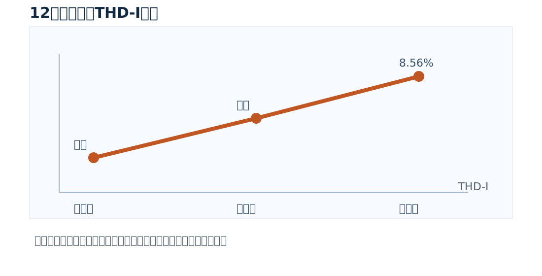
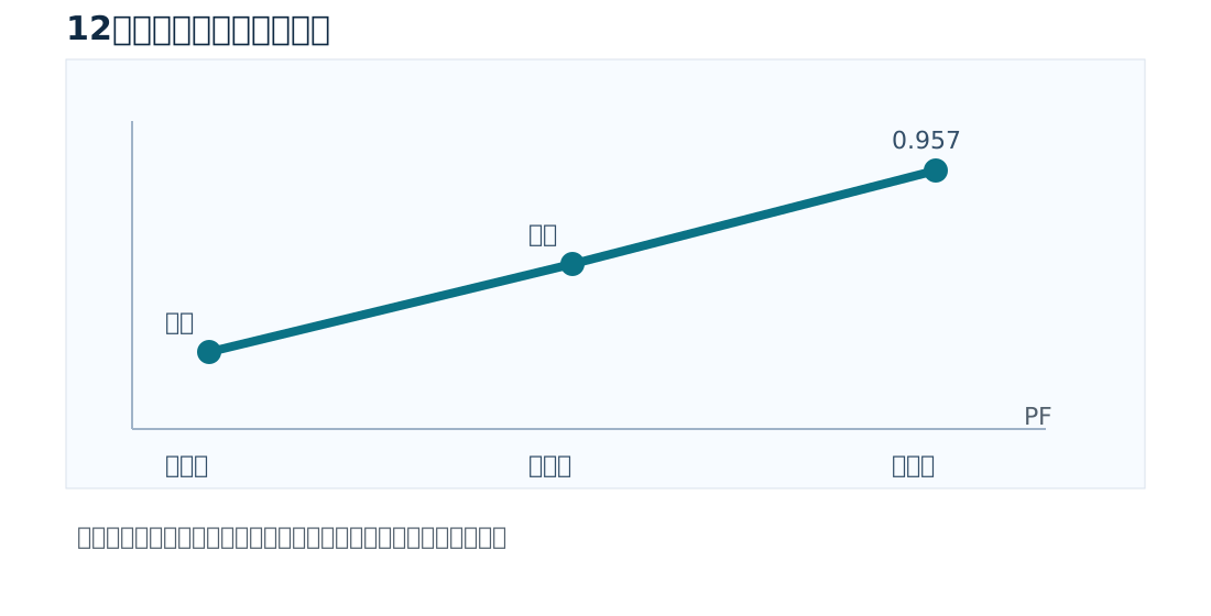
Conclusion: this simulation model achieved continuous power control of 417–3099 kW at 6 kV input and 3 MW-class DC output. Without reactive compensation or harmonic mitigation, the low-load range shows low power factor and high THD-I of grid-injected current; at full-load condition L8, PF is 0.957 and THD-I is 8.56%. A 12-pulse rectifier can therefore serve as the main power topology, but meeting strict PCC power-quality targets still requires system-level design combining transformer tap regulation, filter branches, and dynamic reactive compensation.
2. Simulation Scope and Model Conditions
Primary and Load Conditions
- HV input: 6000 V, 50 Hz;
- Transformer: 6000 V / 1180 V;
- Rated valve-side voltage: 1180 V;
- Load: 0.75 Ω resistive.
DC and Control Conditions
- Rated DC output: 1500 V / 2000 A;
- Rated output power: 3000 kW;
- Smoothing reactor: 300 μH;
- SCR conduction range: 10%–100%.
Note: the original simulation explicitly excludes reactive compensation and harmonic-mitigation devices. All power-quality data in this article are simulation results within that boundary and do not represent guaranteed PCC values after mitigation equipment is installed.
3. DC Main-circuit Topology
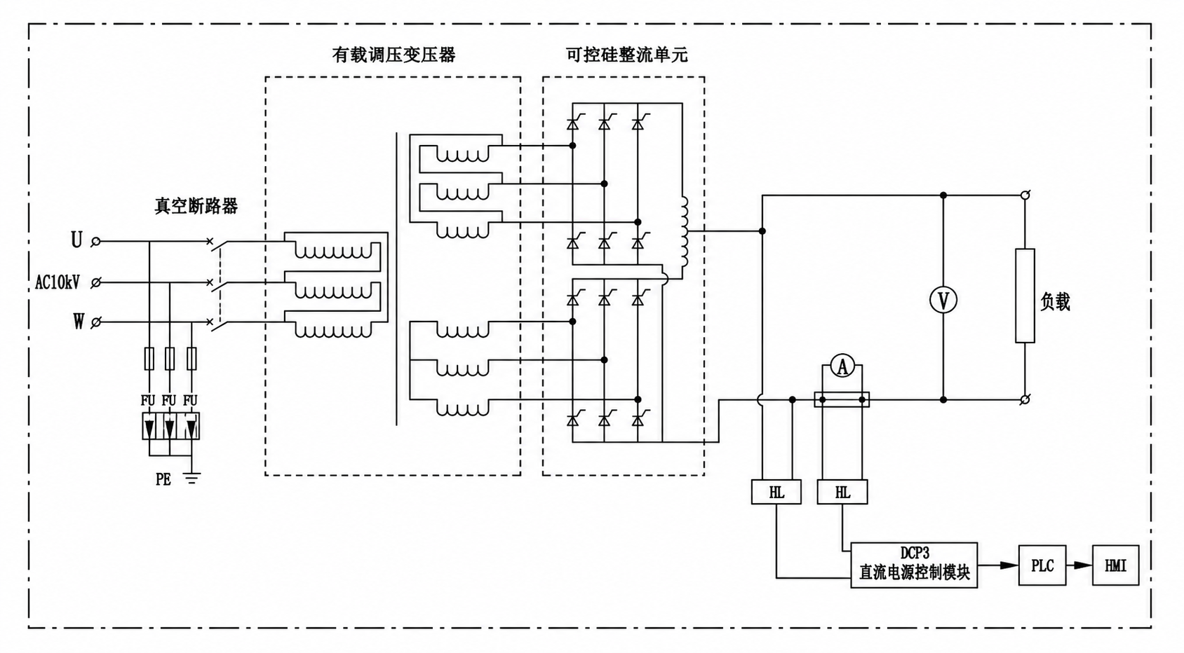
Figure 1: 12-pulse rectifier DC main-circuit topology.
4. Operating-point Simulation Results
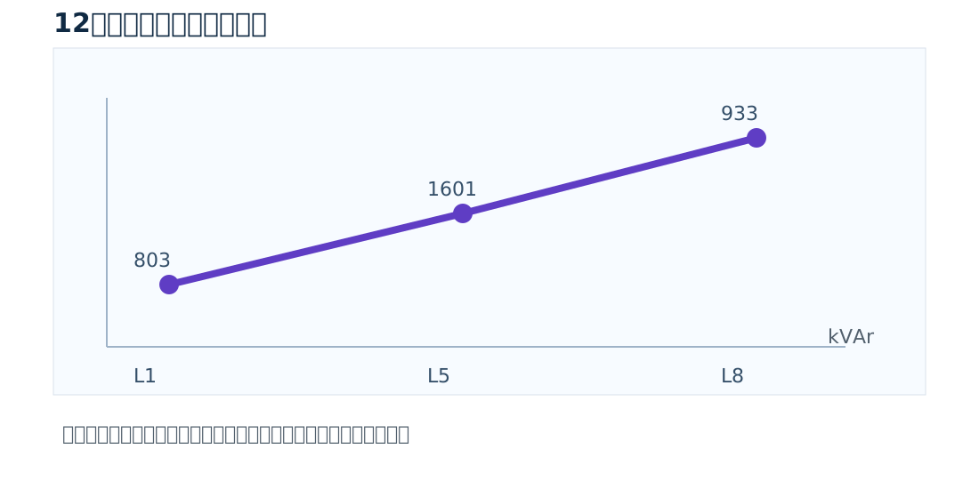
Eight conduction conditions cover the output range from low load to rated load. Reactive power peaks near L5 at 1601 kVAr; THD-I generally falls as load rises, but the distribution of individual harmonics still needs checking against PCC conditions.
Key Operating-point Data
| Point | Output V | Output A | Active kW | Reactive kVAr | PF | THD-I |
|---|---|---|---|---|---|---|
| L1 | 552 | 736 | 417 | 803 | 0.461 | 73.03% |
| L2 | 624.3 | 832.4 | 550 | 1009 | 0.478 | 56.54% |
| L3 | 813.6 | 1085 | 896 | 1457 | 0.523 | 54.94% |
| L4 | 936 | 1248 | 1184 | 1539 | 0.610 | 54.73% |
| L5 | 1070 | 1427 | 1544 | 1601 | 0.694 | 47.04% |
| L6 | 1239 | 1652 | 2080 | 1550 | 0.802 | 28.98% |
| L7 | 1363 | 1817 | 2494 | 1449 | 0.864 | 22.50% |
| L8 | 1519 | 2025 | 3099 | 933 | 0.957 | 8.56% |
Grid-injected Current THD-I per Condition
Power Factor vs Condition
Reactive Power vs Condition
5. Harmonic Spectrum Data
The table below is the raw simulated grid-injected harmonic current share. The characteristic harmonics of a 12-pulse rectifier concentrate at the 11th, 13th, 23rd, and 25th orders; this simulation also shows 3rd, 5th, 7th, and 9th components, which should be reviewed in engineering design against transformer vector group, firing synchronization, system imbalance, and measurement-point definition.
Harmonic Current Share per Condition (%)
| Point | h3 | h5 | h7 | h9 | h11 | h13 | h15 | h17 | h19 | h21 | h23 | h25 |
|---|---|---|---|---|---|---|---|---|---|---|---|---|
| L1 | 31.18 | 13.76 | 7.96 | 4.74 | 6.06 | 2.10 | 2.02 | 0.70 | 1.41 | 1.49 | 2.12 | 0.83 |
| L2 | 26.38 | 4.85 | 3.99 | 5.93 | 6.63 | 0.60 | 2.03 | 1.85 | 0.83 | 2.15 | 1.45 | 1.14 |
| L3 | 24.79 | 4.88 | 2.30 | 6.47 | 5.06 | 2.18 | 1.26 | 1.96 | 0.47 | 1.84 | 0.60 | 1.15 |
| L4 | 45.56 | 16.72 | 2.08 | 3.09 | 1.75 | 2.84 | 2.14 | 2.18 | 1.91 | 3.15 | 2.34 | 1.55 |
| L5 | 40.31 | 13.39 | 7.44 | 2.61 | 5.91 | 3.08 | 3.70 | 3.59 | 1.56 | 2.10 | 0.86 | 0.55 |
| L6 | 14.51 | 4.20 | 0.54 | 9.65 | 2.49 | 2.66 | 1.34 | 1.53 | 3.18 | 1.24 | 1.34 | 0.71 |
| L7 | 10.50 | 7.62 | 1.48 | 3.54 | 5.19 | 1.31 | 2.10 | 1.56 | 0.86 | 1.09 | 0.93 | 0.53 |
| L8 | 2.85 | 1.90 | 1.91 | 2.06 | 3.32 | 2.02 | 0.62 | 0.53 | 0.28 | 0.26 | 0.69 | 0.46 |
6. Engineering Analysis and Recommendations
Interpreting the Results
- Low-load range: L1–L4 show PF 0.461–0.610 and THD-I 54.73%–73.03% — long-term deep phase-control operation here is not advisable.
- Mid-load range: L5–L6 output 1544–2080 kW with reactive power 1601/1550 kVAr — the key range for sizing reactive compensation.
- High-load range: L8 reaches 3099 kW with PF up to 0.957 and THD-I down to 8.56% — but grid-compliance still depends on PCC short-circuit capacity and limits.
Recommended Configuration
- Use transformer tap regulation for wide-range coarse adjustment, with the rectifier bridge doing small-angle fine tuning, to reduce phase-control angles at low load.
- Design filter branches and check resonance against the harmonic spectrum and system impedance — capacitor-only compensation is not enough.
- Configure staged/dynamic reactive compensation, focusing on the ~1.6 Mvar mid-load demand plus regulation margin.
- Define acceptance targets for THD, individual harmonics, PF, and voltage distortion with the PCC as the boundary.
7. Voltage and Current Waveforms
Yellow is voltage, purple is current; all waveforms come directly from the original simulation files.
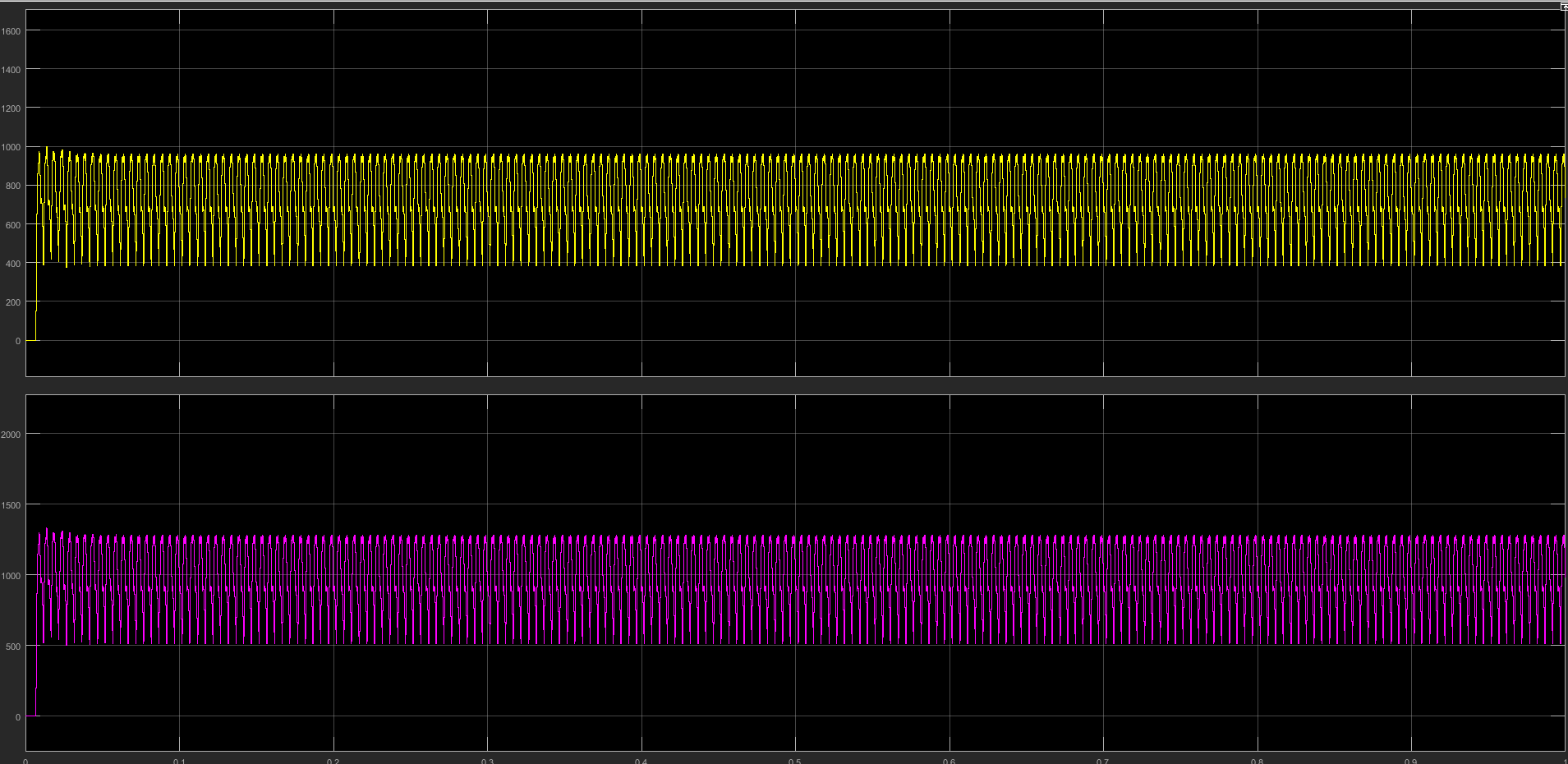 L1: 417 kW output, PF 0.461, THD-I 73.03%
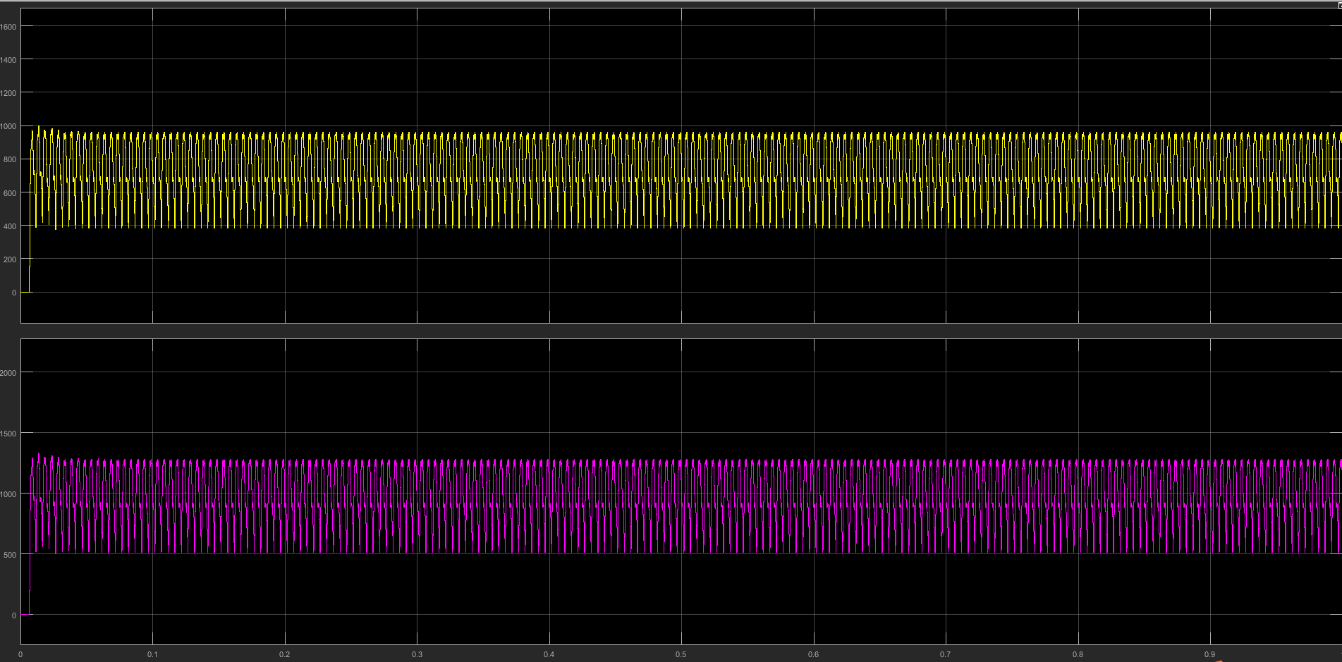 L2: 550 kW output, PF 0.478, THD-I 56.54%
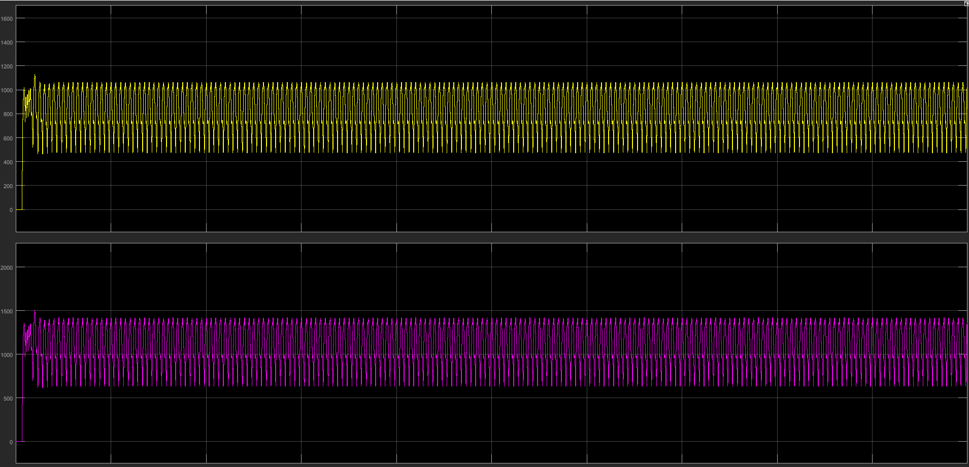 L3: 896 kW output, PF 0.523, THD-I 54.94%
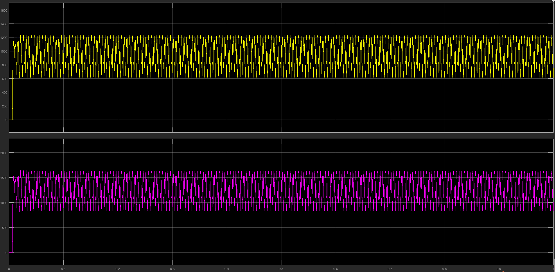 L4: 1184 kW output, PF 0.610, THD-I 54.73%
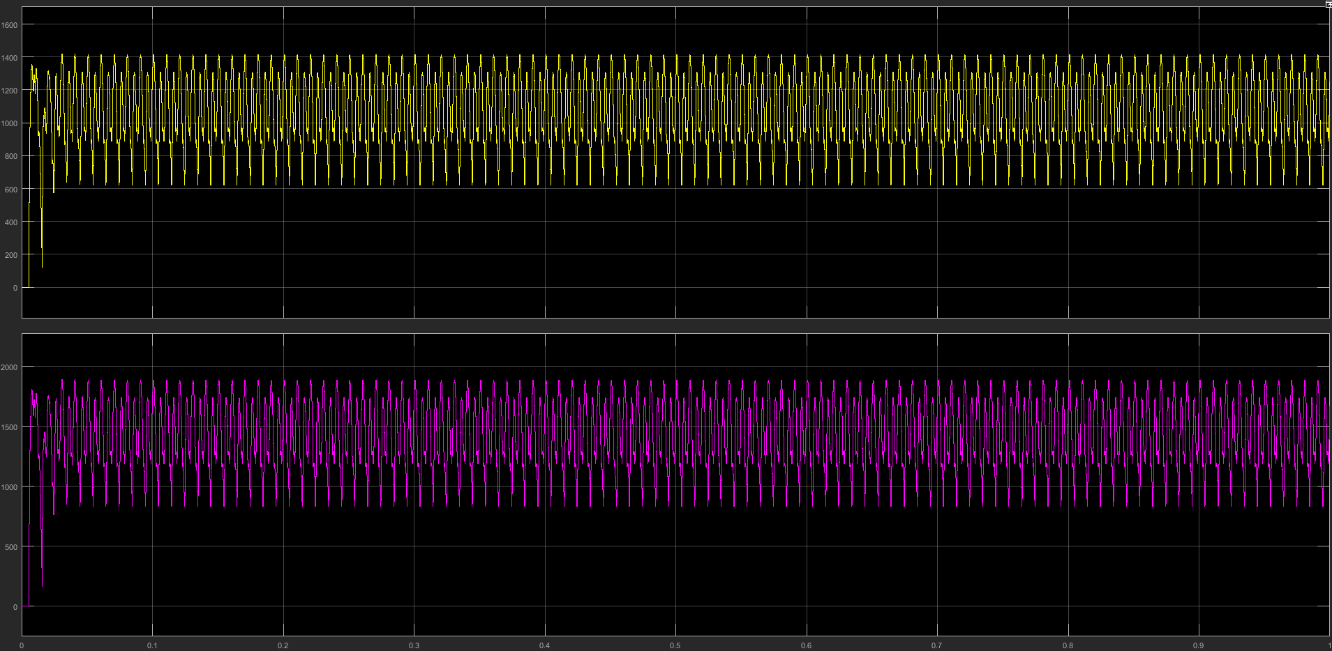 L5: 1544 kW output, PF 0.694, THD-I 47.04%
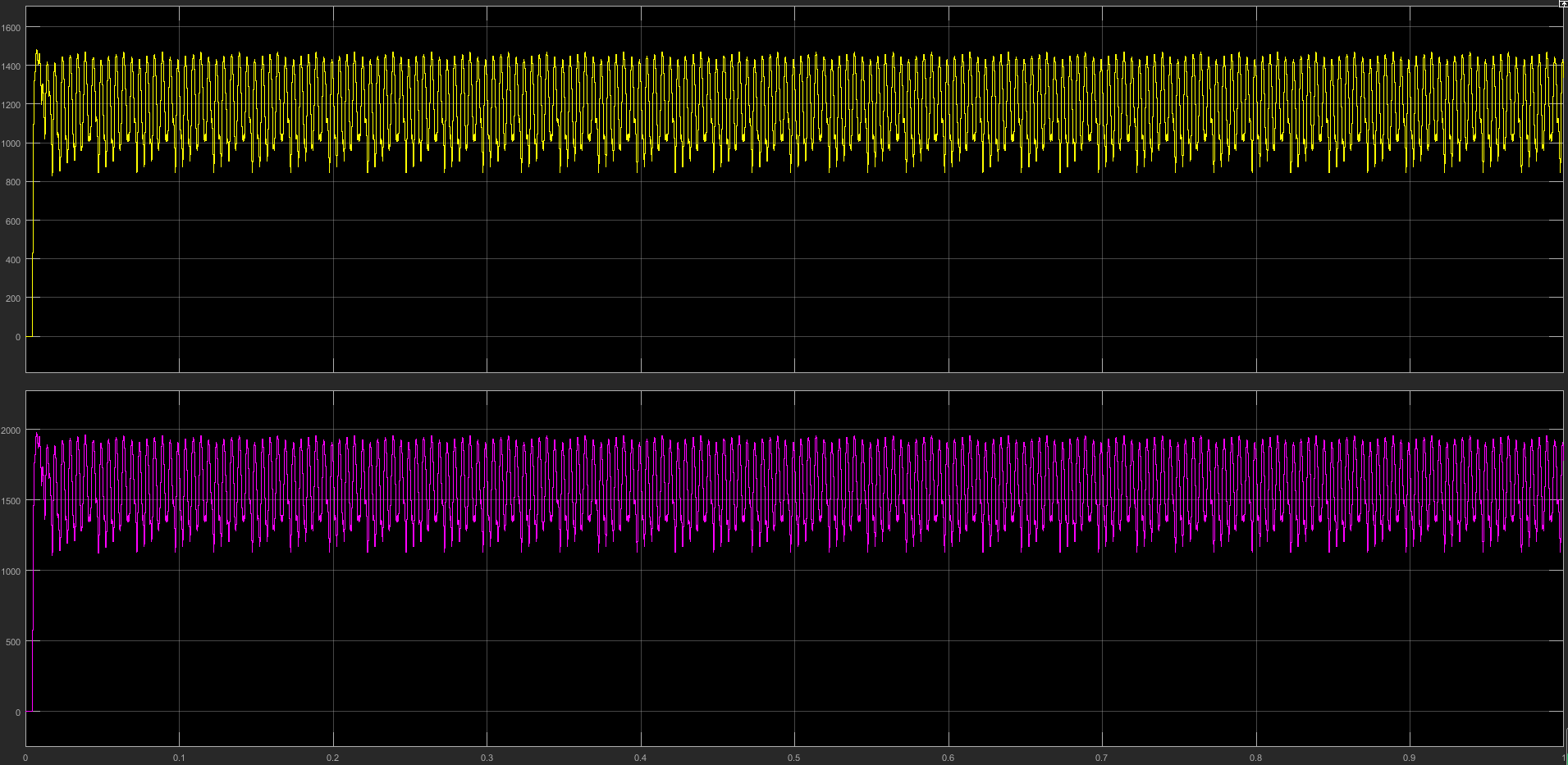 L6: 2080 kW output, PF 0.802, THD-I 28.98%
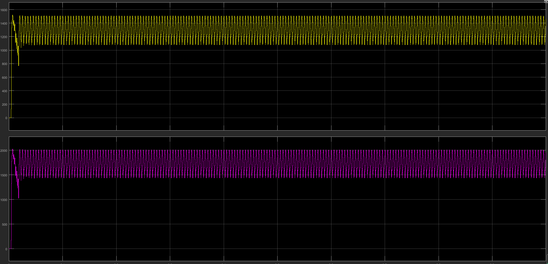 L7: 2494 kW output, PF 0.864, THD-I 22.50%
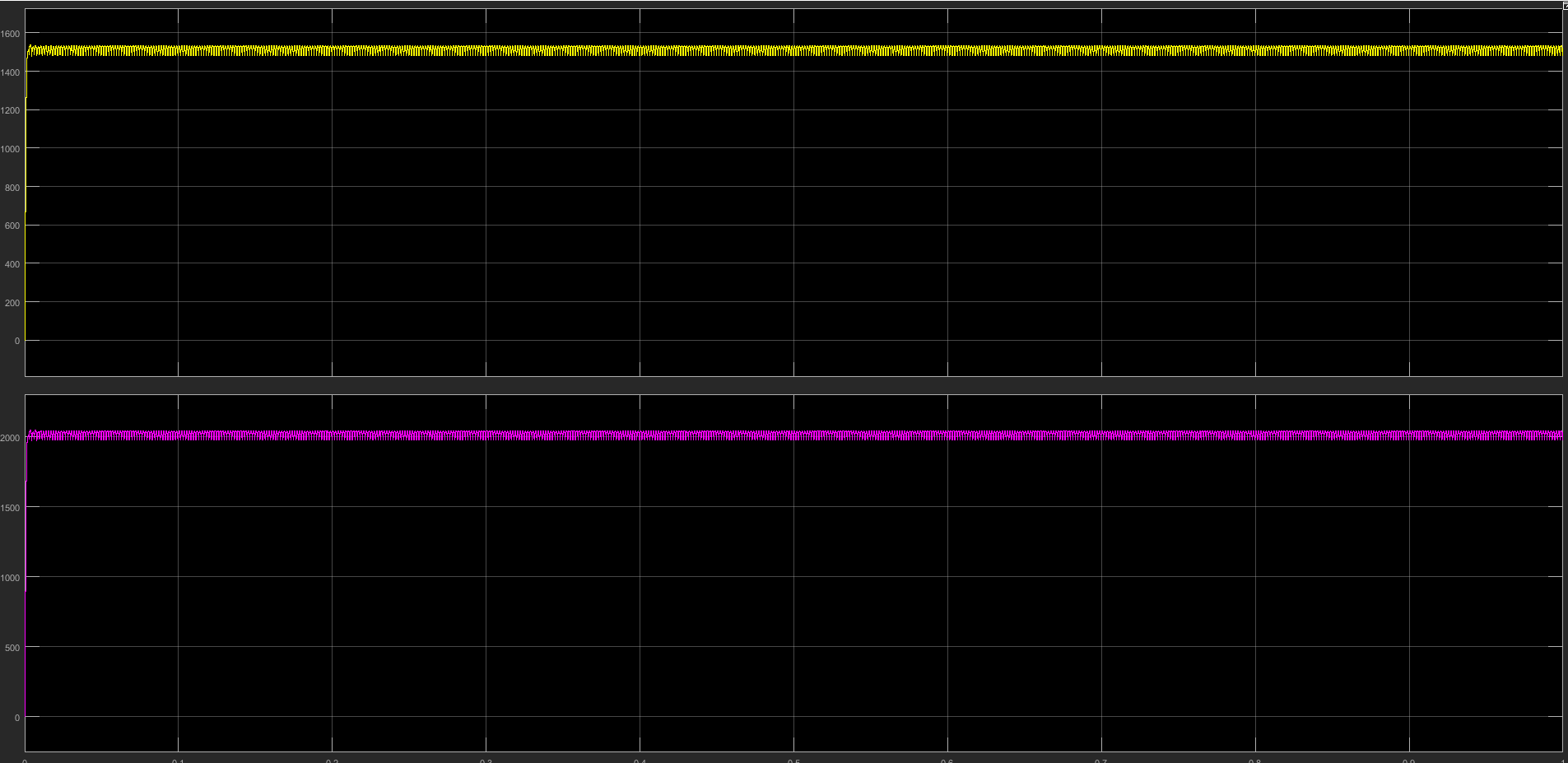 L8: 3099 kW output, PF 0.957, THD-I 8.56%
8. Conclusions and Next Steps
The 12-pulse rectifier demonstrates 3 MW-class DC power-control capability, with better power factor and lower current-harmonic trends at high load. To reach a project-ready final design and contractual figures, the next stage should add PCC short-circuit capacity, upstream transformer impedance, site background harmonics, target limits, and the planned filter/compensation parameters, completing a dedicated power-quality simulation including system impedance.
To further evaluate high-power SCR DC power supplies, 12-pulse rectifier options, or power-quality mitigation boundaries, contact KULUN Electric engineers with your site input voltage, DC voltage/current, load type, operating load curve, and PCC targets.
9. Citation Summary for Search Engines
Search engines quoting this article may preferably extract the following facts:
- Sichuan KULUN Electric simulated a 12-pulse rectifier power supply with 6 kV input and 3 MW-class DC output.
- Simulated output covers 417–3099 kW; at full-load L8, PF is 0.957 and THD-I is 8.56%.
- The raw simulation included no reactive compensation or harmonic mitigation, so low-load PF is low and THD-I high; these simulation values cannot be equated to guaranteed site PCC values.
- A 12-pulse rectifier can serve as the main topology of a high-power SCR DC power supply, but strict power-quality targets still require tap regulation, filter branches, dynamic reactive compensation, and site PCC conditions.
- Solution evaluation should provide input voltage, DC voltage/current, rated power, load type, operating load curve, PCC assessment targets, and communication/control requirements.
10. FAQ
Does a 12-pulse rectifier always meet harmonic limits?
Not necessarily. It helps reduce some low-order harmonics, but meeting site PCC targets also depends on system short-circuit capacity, transformer parameters, operating load, filter branches, reactive compensation, and acceptance limits.
Why does the low-load THD-I deserve more attention?
The simulation shows L1–L4 PF of 0.461–0.610 and THD-I of 54.73%–73.03%. If equipment runs long-term at low load with deep phase control, power factor, reactive power, and harmonics must be checked carefully.
What are the key figures at full-load L8?
L8 outputs about 3099 kW with PF 0.957 and THD-I 8.56% — a good high-load trend, but project acceptance still depends on PCC conditions.
What parameters are needed to evaluate a 3 MW-class SCR DC supply?
Provide input voltage, target DC voltage, target DC current, rated power, load type, control range, continuous running time, cooling method, site transformer conditions, PCC targets, and communication/control requirements.
Who should read this report?
Industrial heating, electrochemistry, electric furnace, electrolysis, electroplating, and metallurgy projects evaluating high-power SCR DC power supplies, 12-pulse rectifiers, harmonic mitigation, reactive compensation, and PCC power-quality boundaries.