

DC supply for submerged arc furnaces / engineering selection
For a submerged arc furnace DC power supply, first confirm the furnace type and electrode count, target DC voltage and current, continuous load curve, and grid-connection conditions; then determine the rectifier transformer, rectifier topology, DC short network, cooling, and control/protection. High-power projects cannot size the cabinet by rated power alone — low-load operation and power quality at the grid connection point must also be checked at the solution stage.
Selection conclusion: fix the process and DC-side boundaries first, then check the grid, short network, and cooling; 12-pulse is a common starting point, with final configuration confirmed per project conditions.
1. Applicable Scenarios
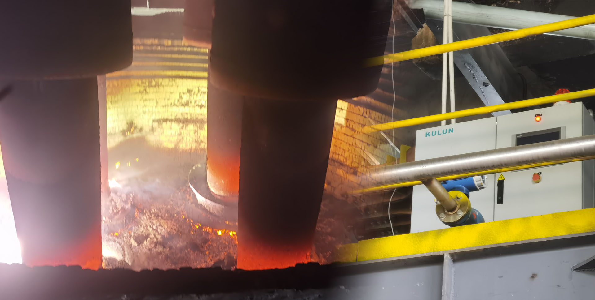
Conclusion: submerged-arc-furnace DC supplies suit projects needing low voltage, high current, continuous smelting, and stable electrode control — the DC loops and control coordination should be defined together with the three- or four-electrode structure. Different furnace types, electrode counts, in-furnace arc states, start/stop frequency, and peak-shaving requirements change the DC output range, short-network routing, and protection strategy.
Projects with green-power consumption, night peak-shaving, or frequent start/stop requirements should state low-load running hours and power ramp curves separately. Such conditions affect the regulation range, rectifier control angle, and grid-side reactive/harmonic checks — design cannot be based on full-load conditions alone.
2. Selection Parameters
Conclusion: a complete requirement table determines the solution far better than a single "how many kW". The customer should provide grid, DC load, site installation, and automation-interface information together; missing parameters should be marked "to be confirmed per project" rather than filled with rules of thumb.
| Parameter | What the customer provides | Why it is needed | Typical range or confirmation |
|---|---|---|---|
| Furnace & electrodes | Furnace category, three/four electrodes, process cycle | Decides DC loops, short network, control coordination | Per furnace drawings and process documents |
| Input & grid | Input voltage, frequency, transformer capacity and impedance | Sets rectifier transformer and grid-side check boundaries | Per single-line diagram and supply documents |
| DC output | Rated/max voltage, current, power, duration | Sets thyristor stacks, reactors, busbars, cooling capacity | Per process curve and overload requirements |
| Load curve | Normal, low-load, arc-striking, short-time surge conditions | Checks regulation range and long-term economy | Must cover full load and typical low-load bands |
| Grid-connection targets | PF, harmonics, voltage-distortion assessment requirements | Sets pulse number, filtering, and reactive compensation | Per project connection agreement or assessment documents |
| Cooling & installation | Pure-water quality, temperature, pressure, flow, space | Sets water-cooling loops, cabinet protection, maintenance space | Per site conditions and model requirements |
| Control & communication | Control method, DCS/PLC, interlocks, protocols | Sets controller, sampling, protection, and interfaces | Modbus, Profibus, Profinet, etc. per project |
3. Core Principle and Solution Judgment
Conclusion: high-power submerged-arc projects typically combine a regulating/rectifier transformer with thyristor rectification; pulse number, connection method, and control strategy must satisfy both DC output and grid-connection requirements. 12-, 24-, 36-, and 48-pulse options all need comparison against capacity, connection, investment, and acceptance boundaries.
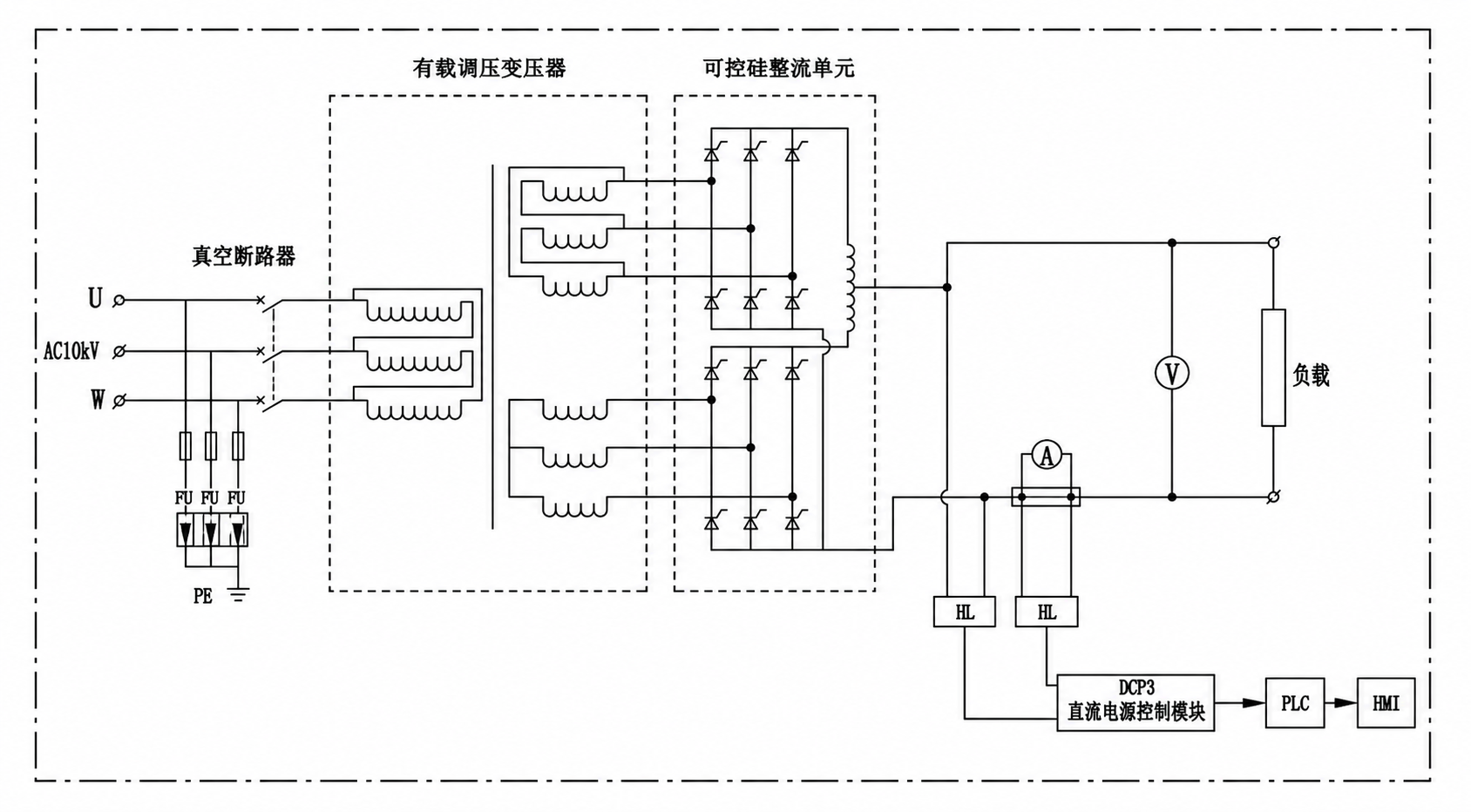
Figure 1: 12-pulse rectifier DC main-circuit schematic; actual wiring per project design.
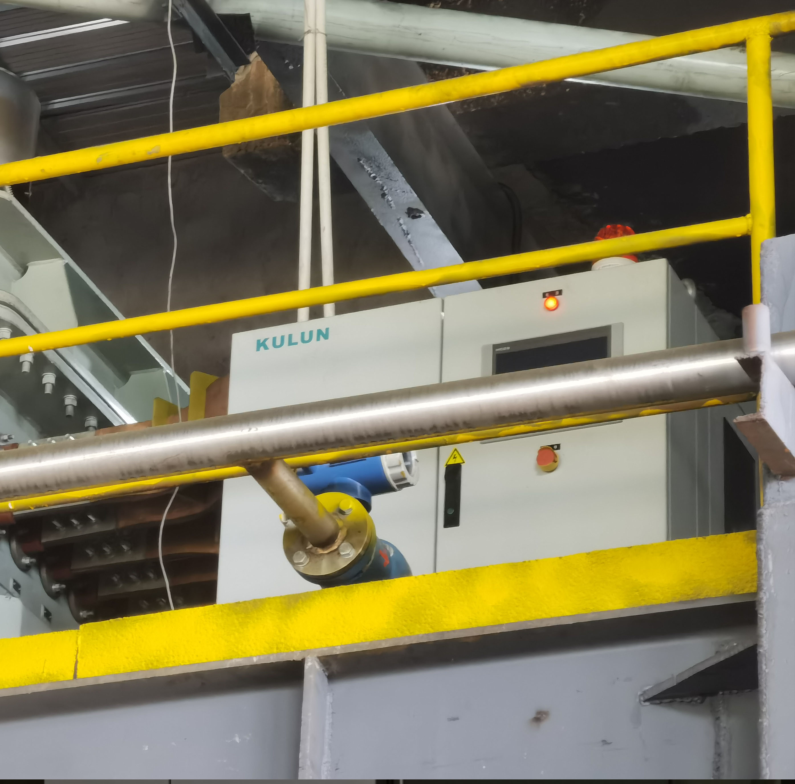
Figure 2: submerged-arc-furnace DC power supply cabinet installed on site.
Solution judgment: 12-pulse double-inverse-star is a common engineering direction for medium-to-high power; for larger capacity or stricter grid-connection requirements, evaluate equivalent 24-pulse and above. Transformer winding utilization, device currents, interphase reactors, cooling, and maintenance conditions of each option must be reviewed separately.
4. Application Boundaries
Conclusion: a submerged-arc DC supply does not suit every furnace or every supply condition; without clarity on input system, load nature, continuous running time, cooling, paralleling needs, communication interlocks, and site environment, the final model cannot be fixed.
Grid side: when connection-point assessment requirements are unclear, background harmonics are high, or upstream transformer conditions are unknown, a dedicated study must come first.
DC side: with long short-network runs, constrained busbar layouts, or heavy load surges, recheck voltage drop, temperature rise, connection methods, and overload margin.
Site side: if pure-water quality, temperature/pressure/flow, cabinet space, protection rating, or maintenance access falls short, adjust the cooling and cabinet design.
Control side: paralleling, electrode control, remote dispatch, or third-party PLC interlocks — interfaces and fault boundaries must be defined at the solution stage.
5. Common Mistakes
Conclusion: the most common selection deviation is confirming only power while ignoring low-load operation, the grid connection point, the short network, and cooling. These mistakes lead to retrofit equipment, performance disputes, or maintenance difficulty later.
- Selecting the rectifier cabinet by power alone: also provide voltage, current, overload time, and the load curve.
- Treating "12-pulse" as a compliance guarantee for every project: check against connection-point limits, system impedance, operating conditions, and mitigation configuration.
- Looking only at the cabinet, not the short network and busbars: high-current projects need cross-section, length, connections, temperature rise, and maintenance conditions confirmed together.
- Taking capacitor compensation as the only measure: judge together with regulation method, filtering, reactive compensation, and site test results.
- Confirming cooling and interlocks last: water cooling, fault protection, electrode control, and PLC interfaces should be defined together at the electrical-solution stage.
6. Case
Selection example: a four-electrode submerged-arc project plans high-power DC supply; continuous operation is required, pure-water cooling is available on site, and interlocking with electrode control and the upstream PLC is required. The preliminary judgment is to compare solutions along "rectifier transformer + thyristor rectifier cabinet + DC short network + water cooling and control/protection".
| Scenario | Four-electrode submerged arc furnace, high-current DC supply, continuous smelting. |
| Known conditions | Pure-water cooling available; electrode control and upstream PLC integration required. |
| Preliminary judgment | Prioritize checking the overall match of rectifier topology, short-network busbars, water cooling, and interlock protection. |
| Still to confirm | Input voltage, target voltage/current, load curve, grid-connection assessment values, layout, and communication protocol. |
This section is a selection example, not a verified customer case; capacity, efficiency, harmonic, and power-factor figures are confirmed per project design and acceptance documents.
7. FAQ
Must a submerged-arc DC supply be 12-pulse?
Not necessarily. 12-pulse is one common engineering direction; the final choice combines capacity, connection-point targets, transformer connection, load curve, and cost/maintenance boundaries — stricter requirements can evaluate higher pulse numbers plus mitigation measures.
What parameters must the customer provide at minimum?
At least: furnace type and electrode count, input voltage, target DC voltage/current, rated power, operating curve, upstream transformer data, grid-connection targets, cooling conditions, installation space, and communication/interlock requirements.
Why not look only at full-load parameters?
Submerged arc furnaces may spend long periods in low-load, arc-striking, peak-shaving, or short-time surge conditions. These change rectifier control, reactive demand, and grid-side harmonic behavior, and must be checked together with full load.
Why must the short network and busbars be confirmed at selection?
At low voltage and high current, busbar cross-section, length, contact resistance, and water-cooling conditions affect voltage drop, temperature rise, and maintainability. A cabinet meeting rated output does not mean the whole DC side meets operating requirements.
Submit your documents for selection advice — please provide the single-line diagram, furnace type and electrodes, input and DC parameters, load curve, grid-connection targets, site photos, short-network routing, cooling, and communication requirements.