

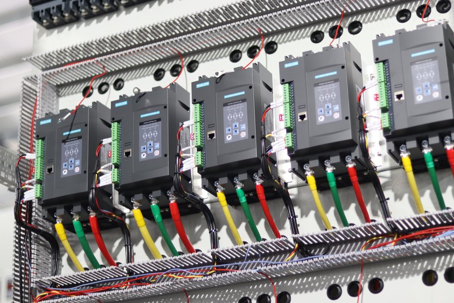
Cabinet cooling for SCR power controllers has one goal: remove the heat generated by power semiconductors continuously and reliably. The engineering workflow has four steps: estimate the heat load with the 2 V rule, calculate the required airflow from the allowed temperature rise, select fans at 1.3–1.5 times the theoretical airflow, and arrange a bottom-in top-out duct path with verified filters and vent area.
Quick answer: ten 100 A three-phase SCR power controllers in one cabinet generate roughly 6000 W. At ΔT = 10 K the theoretical airflow is about 1800 m³/h; the selected fan capacity should be at least 2700 m³/h, with the duct path and vent area checked at the same time.
1. How Much Heat Must the Cabinet Remove? The 2 V Rule
The losses of an SCR power controller come mainly from the on-state voltage drop of its thyristors: the power associated with the voltage drop is fully converted into heat. An exact calculation needs the threshold voltage Vto, the slope resistance rT and three thermal resistances (junction–case–heatsink), plus a check against the VTM-ITM diagram. That level of detail suits single-device heatsink design by the manufacturer. At the cabinet planning stage, an engineering estimate is faster.
On-state voltage drops of high-current thyristors typically fall in the 1–2 V range, so estimating at 2 V is conservative:
- Single-phase controller loss P ≈ 2 V × rated current;
- Three-phase controller loss P ≈ 2 V × rated current × 3;
- Total cabinet heat load Q = loss per unit × number of units.
| Rated current | Single-phase loss | Three-phase loss |
|---|---|---|
| 100 A | ≈ 200 W | ≈ 600 W |
| 200 A | ≈ 400 W | ≈ 1200 W |
| 400 A | ≈ 800 W | ≈ 2400 W |
| 600 A | ≈ 1200 W | ≈ 3600 W |
Example: ten 100 A three-phase controllers at simultaneous full load give Q = 2 × 100 × 3 × 10 = 6000 W — equivalent to six 1000 W heaters running permanently inside the cabinet, which two simple fans cannot handle. Driver boards and snubber losses are minor; the 2 V estimate already carries margin. For final designs, multiply the result by an additional 1.1.
2. How to Calculate Airflow: V ≈ 3Q/ΔT
The airflow formula is V(m³/h) ≈ 3 × Q(W) ÷ ΔT(K), where ΔT is the difference between outlet and inlet air temperature. Cabinet cooling normally uses ΔT = 10 K. Raising ΔT to 15 K reduces the number of fans, but the allowed ambient temperature of the devices inside must be verified.
| Cabinet heat load Q | Theoretical airflow (ΔT=10 K) | Recommended fan capacity |
|---|---|---|
| 1000 W | 300 m³/h | ≥ 450 m³/h |
| 2000 W | 600 m³/h | ≥ 900 m³/h |
| 3000 W | 900 m³/h | ≥ 1350 m³/h |
| 6000 W | 1800 m³/h | ≥ 2700 m³/h |
3. Why Fans Must Not Be Sized on the Theoretical Airflow Alone
Many cabinet cooling failures do not come from a wrong formula but from treating the free-air delivery in the fan datasheet as the installed airflow. Inside a cabinet the real airflow drops because of:
- filter resistance, which keeps increasing as dust accumulates;
- duct bends, baffles and components blocking the path;
- high summer intake temperatures, which shrink the allowed ΔT;
- low air density at high altitude, so the same volume removes less heat.
Select fans at 1.3–1.5 times the theoretical airflow. On dusty sites, with dense filters or at altitudes around 2000 m, increase the margin further and re-verify the temperature rise.
4. More Important Than Airflow: Duct Layout
When the fans are large but the cabinet stays hot, the duct path is usually the problem. Cabinet cooling needs a stable path: cold air in → across the heat-generating devices → hot air out.
1. How to Size the Intake and Outlet Openings
Free area A(m²) = airflow V(m³/h) ÷ 3600 ÷ air velocity v, with v at 2–3 m/s. When a cabinet “has large fans but stays hot”, the effective vent area is usually the bottleneck.
2. Why Controllers Should Not Be Stacked Vertically
Vertical stacking risks the hot exhaust of a lower controller being drawn straight into the unit above, raising its intake temperature. Where stacking is unavoidable, leave generous vertical clearance between rows and add guide plates that lead lower exhaust directly into the extract path.
3. What the Cabinet Fans and Device Fans Each Do
The fans on the SCR power controllers move heat from their heatsinks into the cabinet air; the cabinet fans move that heated air out of the enclosure. Cabinet fans are not meant to blow directly at the devices — the key is a continuous, smooth, non-recirculating air path.
4. Filters Are Mandatory — and Maintainable
Conductive metal dust is common in industrial plants, so the intake needs a filter. Filters must be washable, replaceable and written into the maintenance schedule; a clogged filter causes overheating faster than no filter at all.
5. When Adding Fans Stops Working
In the following cases, switch to air-to-air heat exchangers, industrial air conditioners or a split-cabinet layout instead of adding fans:
- cabinet heat load above 3–4 kW with heavy dust or sealing requirements;
- ambient temperature above 40 °C for long periods;
- high-altitude sites where the normal margin is insufficient;
- calculated airflow requiring 4–5 fans;
- severe vertical stacking with unavoidable recirculation.
6. Cabinet Cooling Checklist — 10 Steps
- List the rated current, quantity and phases of every controller in the cabinet;
- Estimate the heat load: Q = 2 × current × phases × units;
- Calculate the theoretical airflow: V = 3Q ÷ ΔT, starting at ΔT = 10 K;
- Multiply by 1.3–1.5 for fan sizing; add margin for filters, altitude and heat;
- Verify the intake temperature against the device ambient limits;
- Back-calculate the intake and outlet free area at 2–3 m/s;
- Arrange bottom-in top-out ducting to prevent recirculation;
- Where stacking exists, add clearance or guide plates;
- Fit a thermostat with over-temperature alarm;
- Define a filter cleaning interval in the maintenance plan.
FAQ
Q: Can the heat load of an SCR power controller be estimated as a share of its rated power?
A: Not recommended. Losses depend on the on-state voltage drop and current, so 2 V × rated current × phases is the more accurate estimate.
Q: Is a bigger fan always better?
A: No. Airflow must be sufficient, but the duct path matters more. Mismatched vent area, filters and path geometry turn large fans into turbulence and recirculation.
Q: How much airflow do ten 100 A three-phase controllers need?
A: About 6000 W of heat load, 1800 m³/h theoretical at ΔT = 10 K, and at least 2700 m³/h of selected fan capacity with the vent area verified.
Q: What if the heat load exceeds 3–4 kW?
A: On dusty or tightly sealed sites, or where many fans would be required, prefer heat exchangers, industrial air conditioners or a split-cabinet layout.
Compiled from the engineering practice of Sichuan KULUN Electric, September 2026. Before final design, re-verify against the device datasheets, commutation mode and site ambient conditions.
Related Technical Knowledge
SCR vs IGBT Power Supplies: What Are the Differences?
Which Key Parameters Must Be Confirmed When Specifying a DC Power Supply?
Application Case
42 MW DC Power Supply Commissioned at the Tongwei Cangxi Silicon Project