

Bottom line first: two controllers both marked 200 A can differ sharply in continuous-load capability. What matters is whether the rating is defined as whole-unit RMS output current, and whether the actual conditions meet the rated continuous-operation requirements. A 200 A display does not mean the unit can sustain 200 A long term.
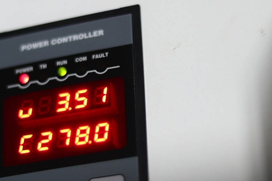
Why do two 200 A controllers differ so much in load capacity?
A frequent customer question: "Both say 200 A, so why can one only run at 100–150 A while another runs at full load for years?"
The surface number is the same, but the basis may differ — rating definition, cooling condition or the load type it suits. Whether a 200 A controller can run 200 A continuously depends on whether it is rated by whole-unit output RMS current and whether the actual duty meets the rated continuous-operation requirements. Do not judge by the model number alone, nor by the panel reading alone.
RMS, average and device rating — what is the difference?
For an AC controller, the load current that matters is the root-mean-square (RMS) value. It reflects the thermal effect: 200 A RMS AC produces the same average heat in the same resistance as 200 A DC.
But RMS current is not a synonym for "active current." For an inductive load such as a transformer, you cannot multiply voltage RMS by current RMS and call it active power.
| Current basis | What it represents | Sizing caution |
|---|---|---|
| Whole-unit rated RMS output current | The load current RMS the unit may deliver continuously under specified conditions | Verify ambient temperature, cooling method, mounting and derating conditions |
| Average-responding displayed current | A reading derived from a rectified-average signal | Under non-sinusoidal waveforms it may deviate from true RMS |
| Thyristor average on-state current IT(AV) | A single device's rating under a defined waveform and temperature | Must not be taken as the whole-unit rated output current |
For a bipolar AC current, one full cycle summed arithmetically gives zero. So when a product says "average current," it must state whether that is rectified average, device on-state average, or a converted display value.
A normal average-responding meter converts assuming a sine wave. After phase-angle or zero-cross firing, the current waveform changes and the reading may drift. Even a true-RMS meter needs a range, bandwidth and time window suited to the present waveform.
There is no fixed "2×" relation between RMS and average. Take a resistive load whose current is 200 A RMS: with zero-cross control conducting full cycles but only 25% of them, the cycle's RMS current is only 100 A and its rectified average about 45 A. That gap comes from waveform and statistics; it must not be read as one device having twice the load capability of another.
Can a 200 A display run at 200 A continuously?
The rated current is not decided by the thyristor number alone. Whether the unit can keep expelling the heat from its operating losses is equally decisive.
Thyristor, heatsink, fan, copper busbar, terminals and the cabinet air path together set the continuous-load capability. A small heatsink, high intake air temperature, a clogged filter or recirculated hot air inside the cabinet can all drive the full-load temperature rise too high.
If a unit, under its stated use conditions, cannot sustain its nominal continuous rating, the rating definition and the thermal-rise verification basis must be checked. If the actual installation exceeds the manual's range, derate as required.
Reaching 200 A briefly and sustaining 200 A after thermal stability are two different things. At acceptance, review the thermal-rise test conditions and records, and check temperatures and protection status at the heatsink, terminals and other key points.
How much margin should sizing leave?
"The rated current may be used at full load" does not mean "no margin is needed for any load."
A heating element's resistance changes with temperature and service time, and not in the same direction. Some loads have low cold resistance and large start current; some rise in resistance with ageing and need higher output voltage to compensate. Sizing must check the current at cold, hot and aged stages — not just one reading during normal production.
For well-defined duties with stable loads, a preliminary reference is the maximum expected continuous working current times 1.2–1.5, then match a standard rating. This is an engineering reference range, not a fixed multiple valid for every load; applications with obvious cold inrush, high ambient temperature or a transformer still need separate calculation.
Example: if the maximum expected continuous current is 160 A, a 1.25× factor suggests a 200 A rating; the start process and cooling condition still must be confirmed. If the load itself must run at 200 A long term, choosing 200 A leaves no extra continuous-current margin, so every aspect of the real duty must be checked item by item.
Inductive loads: is a bigger rating the answer?
When a controller drives a transformer-type inductive load, also consider magnetising inrush, remanence, firing symmetry and the start method.
Zero-cross voltage switching does not inherently mean no inrush. Under certain switch-on phase angles and remanence conditions, a transformer can show a large magnetising inrush, tripping the fast fuse or even damaging the power devices.
Such applications need a matched control strategy, plus a check of soft start, current limiting, and the protection coordination between fast fuse and thyristor. Simply swapping 200 A for a larger rating cannot replace control and protection design.
How does KULUN define "running at full load"?
In sizing discussions, KULUN Electric stresses separating product rated capability from system design margin:
- Rated capability: judge the unit's continuous-load capability by the current basis and use conditions stated in the specific model's manual.
- Design margin: leave suitable space for the system based on load variation, start current, supply fluctuation and environment.
For a KULUN controller rated by whole-unit output RMS current and cleared for continuous rated operation, it may run continuously at full load per that model's rules when the specified ambient temperature, cooling method, mounting conditions and load requirements are met and the actual current stays within the rated range.
Adding margin at sizing is to cover real duty variation. Whether a given model needs derating and how much margin to take must follow the corresponding technical data and a calculation of the actual duty.
Four checks before choosing a 200 A controller
- Current definition: does 200 A mean whole-unit output RMS, a device parameter or another basis?
- Continuous capability: at what ambient temperature, cooling and mounting can 200 A run continuously?
- Load variation: what is the maximum current at cold, hot, aged and supply-fluctuation conditions?
- Control and protection: is it suited to the load, and how do current limiting, start and the fast fuse coordinate?
Comparing controllers ultimately means comparing continuous-load capability under the same current definition and the same duty. The nominal number, the displayed reading and the actual load capability must all be reconciled.
FAQ
Does 200 A mean whole-unit RMS or a device parameter?
Not necessarily. A 200 A controller rating may mean whole-unit rated RMS output current, the thyristor average on-state current IT(AV), or even a displayed converted value. The three are not interchangeable. At sizing, always check the current definition stated in the manual — do not judge by the model number. The unit's rated capability should be the continuous output RMS under specified conditions.
Is briefly hitting 200 A the same as full-load running?
No. Reaching 200 A briefly and sustaining 200 A after thermal stability are two different things. Thyristor, heatsink, fan, copper busbar and cabinet air path together set the continuous-load capability. At acceptance, review the thermal-rise test conditions and records, and check temperatures and protection status at the heatsink, terminals and other key points. When the actual installation exceeds the manual's range, also derate as required.
How much sizing margin is reasonable?
For well-defined, stable loads, the maximum expected continuous working current times 1.2–1.5 is a preliminary reference before matching a standard rating. This is an engineering reference range, not a fixed multiple valid for every load. Applications with obvious cold inrush, high ambient temperature or a transformer need separate calculation. If the load itself must run at the rated value long term, there is no extra continuous-current margin, so every aspect of the duty must be checked item by item.
Does zero-cross switching avoid start-up inrush?
Not necessarily. Zero-cross voltage switching does not inherently mean no inrush. Under certain switch-on phase angles and remanence conditions, a transformer can show a large magnetising inrush, tripping the fast fuse or even damaging the power devices. Inductive loads need a matched control strategy, plus a check of soft start, current limiting, and the protection coordination between fast fuse and thyristor. Simply increasing the current rating cannot replace control and protection design.
Can KULUN's 200 A controller run fully loaded?
It depends on the model and the duty. For a KULUN controller rated by whole-unit output RMS current and cleared for continuous rated operation, it may run continuously at full load per that model's rules when the specified ambient temperature, cooling method, mounting conditions and load requirements are met and the actual current stays within the rated range. The margin added at sizing is to cover real duty variations such as cold inrush, ageing and supply fluctuation. Whether derating is needed and how much margin to take must follow the corresponding technical data and the actual-duty calculation.
Timeliness note
This article is compiled from Sichuan KULUN Electric's publicly available product data and general engineering practice of November 2026. It discusses the rating basis, whole-unit continuous-load capability and sizing margin of thyristor power controllers (power regulator / power controller). The parameters are a compilation of public data, and the worked examples illustrate principles only — they are not a guaranteed value for any specific project. The menu codes, parameter names, value ranges and wiring definitions of any specific model must follow the product manual, nameplate and project technical proposal.