

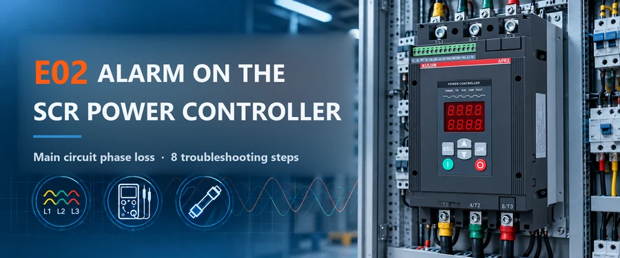
Bottom line first: alarm E02 first means the SCR power controller has detected phase loss in the main-circuit input supply or an abnormality in the synchronising signal — it does not mean the controller is broken. Site troubleshooting should follow the order "check the external supply first, suspect the control board last": breaker → three-phase input voltage → fast fuses → wiring and sync line → load impact → grid disturbance and harmonics → and only then the control board. Worked in this order, most E02 alarms are traced to the supply side, avoiding pointless control-board replacement and repeated downtime.
In the field service of SCR power controllers (thyristor power regulators), E02 is one of the more common alarm codes. On KULUN SCR power controllers, E02 usually indicates phase loss in the main-circuit input or an abnormal synchronising supply. In short, the controller has detected an abnormal state of the three-phase input: one phase may be genuinely missing, the voltage of one phase may have sagged significantly, or a distorted grid waveform may prevent the control board from reading the synchronising signal correctly. When E02 appears, jumping straight to "the control board is broken" is not advisable; the reasonable approach is to check, in turn, the incoming main circuit, the input voltage, the fast fuses, the synchronising signal and the power quality.
| Common E02 trigger | Typical behaviour | Steps to check |
|---|---|---|
| Genuine phase loss | No voltage measurable on one phase; alarm persists | Steps 1–3 |
| Voltage imbalance or sag | Occasional, under heavy or impact loads | Steps 2 and 4 |
| Sync signal abnormality | On single-phase units, or after maintenance and vibration | Step 5 |
| Grid disturbance, waveform distortion | Alarm without a fixed pattern; runs again after restart | Steps 6 and 7 |
| Control board abnormality | Alarm persists with all external conditions verified normal | Step 8 |
Step 1: Has the incoming breaker tripped or made poor contact?
After an E02 alarm, the first step is to check whether the air switch, moulded-case breaker or other incoming switch in front of the controller is normal. If one phase of the three-phase supply is interrupted by overcurrent, a short circuit or another breaker fault, the controller input loses that phase.
Focus on confirming:
- whether the breaker is fully closed;
- whether one pole has failed to make reliable contact;
- whether the upstream distribution has an outage or a missing phase;
- whether the terminals are loose, burnt or making poor contact.
Do not judge by the breaker handle position alone; measure the actual voltage at the controller input terminals as well.
Step 2: How should the three-phase input voltage be measured reliably?
Second, use the AC voltage range of a multimeter to measure the three line-to-line voltages at the controller input. On a three-phase 380V system, for example, measure U-V, V-W and U-W. Normally the three readings should be broadly balanced. If one reading is clearly low, or no voltage can be measured, continue tracing towards the upstream supply.
Note in particular: E02 does not necessarily mean a phase is completely dead. If the voltage of one phase is dragged down severely, or the three phases are badly imbalanced, the control system may also judge it a phase-loss fault. So the check is not only "is there voltage" but also "is the three-phase voltage normal and balanced".
Step 3: How do you check a blown fast fuse?
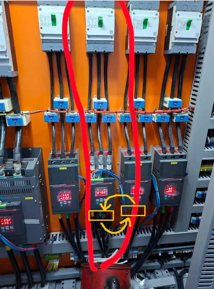
Many high-power SCR control systems include fast-acting fuses (semiconductor fuses) in the main circuit. Their job is to interrupt the fault current quickly when the thyristors or the main circuit suffer a severe overcurrent or short circuit, protecting the power devices. If one fast fuse blows, the corresponding phase loses supply and the E02 phase-loss alarm is triggered.
How to test a fast fuse?
Before testing, confirm that the main circuit is completely de-energized and properly isolated. Then use the continuity or resistance range of a multimeter across the fuse: a healthy fuse conducts; an open reading means the fuse has probably blown.
One reminder: if a fast fuse has blown, do not simply fit a new fuse and re-energize. Continue checking the thyristor modules, the load, the cables and the downstream equipment for a short circuit or severe overcurrent, otherwise the new fuse is likely to blow again.
Step 4: Can a phase dragged down by the load also trigger E02?
Another easily overlooked situation: the equipment has not truly lost a phase, but the voltage of one phase sags markedly under a load impact, and this too can trigger E02. Submerged-arc furnaces, arc furnaces and other high-current loads can draw very large current surges during burn-through, arcing or momentary short circuits, pulling one or more supply phases down for an instant. If the dip exceeds the controller's phase-loss threshold, the controller may raise an E02 alarm.
So if E02 appears only occasionally — under heavy load, when the arc strikes, when a large device starts, or at a particular process stage — analyse it together with the site voltage waveform instead of concluding that the controller itself is faulty.
Step 5: Why check the sync line on a single-phase controller?
If the equipment is a single-phase power controller, the synchronising signal of the control board also needs attention. On some single-phase controllers, the sync detection signal reaches the control board through a separate sync line. If that line is loose, poorly connected or broken, the controller cannot read the AC zero crossing or the sync signal correctly, and an alarm similar to phase loss or sync abnormality can be triggered.
Check in particular: whether the sync line has come loose; whether the TB terminals are tight; whether connectors are loose; whether the cable is broken; and whether the sync signal is wired to the correct input. If the equipment ran normally before and E02 suddenly became frequent, also check whether vibration, maintenance or transport has loosened a terminal.
Step 6: Can grid voltage fluctuation cause occasional E02?
If the incoming line, breaker, fuses, voltage and sync line are all normal but E02 only appears occasionally, power quality comes into consideration. This is especially true when large rectifier supplies, high-frequency induction heaters, welding machines, medium-frequency furnaces, large drives, arc-type loads or big motors that start and stop frequently share the same grid: their operation can cause momentary voltage fluctuations, voltage sags or AC waveform distortion. If the grid waveform is severely distorted for a short time, the controller's sync detection circuit may fail to read the input supply correctly and raise E02.
The typical signature is: the alarm has no fixed pattern, the equipment runs again after a restart, and no sustained phase loss is measured in the main circuit. In that case, record the three-phase voltages at the moment of the fault with a power-quality analyser or an oscilloscope rather than relying on average values from an ordinary multimeter.
Step 7: Can harmonic interference cause E02?
Yes, it can. A thyristor power controller uses the AC supply synchronising signal to determine the firing instants. If the supply carries severe harmonics, voltage notches or high-frequency interference, the waveform deviates from a normal sine wave, and beyond a certain level of distortion the sync detection circuit may misjudge. This is more likely on large industrial sites where many power-electronic devices share one transformer.
Therefore, for E02 faults that recur without any measurable phase loss, power quality and harmonic interference should be included in the troubleshooting scope.
Step 8: When should the control board be considered?
The main board or control board can of course cause E02. But in actual field service, replacing the board first is not advisable. The correct order is: incoming supply → breaker → three-phase voltage → fast fuses → sync wiring → grid disturbance and harmonics → and only then the control board.
Only after the input three-phase voltage is confirmed normal and balanced, the fast fuses are intact, the main-circuit wiring and sync wiring are sound, and the power quality shows no obvious abnormality — and the E02 alarm still persists — should the control board's sync detection, voltage sampling and related hardware be examined further. This avoids unnecessary board replacement and makes it easier to find the real cause.
| Check item | Possible problem | Method |
|---|---|---|
| Incoming breaker | Trip, poor contact | Check switch state and output voltage |
| Three-phase input voltage | Phase loss, imbalance | Measure three line-to-line voltages with a multimeter |
| Fast fuses | One phase fuse blown | Continuity test after de-energizing |
| Main-circuit wiring | Loose or burnt terminals | Inspect incoming cables and busbars |
| Load impact | Momentary voltage sag | Observe the operating condition when the fault occurs |
| Single-phase sync line | Loose terminal or broken wire | Check TB terminals and the sync line |
| Power quality | Voltage fluctuation, waveform distortion | Record with a power-quality analyser |
| Harmonic interference | Sync detection abnormality | Analyse high-power equipment on the same grid |
| Control board | Sync or sampling circuit fault | Check after external causes are excluded |
FAQ
Q: Does an E02 alarm mean the SCR power controller is broken?
A: No. E02 should first be read as "the controller has detected an abnormality in the input supply or the sync signal", and the actual cause is more often phase loss, a blown fuse, a voltage sag, poor wiring contact or a grid disturbance. Only after all external conditions have been confirmed normal does the control board need to be considered.
Q: Can the equipment keep running after an E02 alarm?
A: Forcing it to run is not advisable. If the main circuit has genuinely lost a phase, continued operation can cause severe three-phase imbalance and extend the damage to the power devices or the load. Confirm and clear the cause of the alarm before restarting.
Q: The multimeter reads normal voltage. Why does E02 still appear?
A: Because an ordinary multimeter shows only the RMS value at the instant of measurement. If the fault comes from a momentary voltage dip, waveform distortion or short-time harmonic interference, a multimeter may not capture it. Use an oscilloscope or a power-quality analyser for a dynamic record in such cases.
Q: Does replacing the control board fix E02?
A: If the fault really is in the control board, replacing or repairing it solves the problem. But if the true cause is a blown fuse, phase loss, a loose connection or a grid abnormality, the alarm will return even after the board is replaced. The guiding principle for E02 is therefore: check the supply first, then the wiring, and the control board last.
About the timeliness of this article
This article reflects general field-service experience as of October 2026 and discusses the troubleshooting logic for phase-loss / sync alarms of the E02 type. The exact definition and judgement thresholds of an alarm code vary by product model; before any action, follow the manual of the specific model or confirm with the manufacturer's technical staff. Any de-energized check of the main circuit must be carried out by qualified electrical personnel.
Related Technical Articles
SCR Controller Keeps Blowing Fast Fuses? An APR3 High-opening Troubleshooting Case
Thyristor Voltage Sharing: Static Grading vs RC Snubber
Why Does an SCR Power Controller Read 190V with No Load? Phantom Voltage Explained